
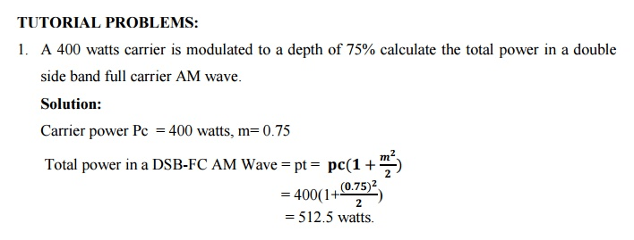
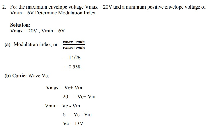
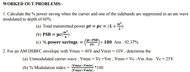
AM Transmitters
An AM Broadcast Transmitter is a device used to transmit AM (Amplitude Modulation) radio signals. It takes an audio signal from a mixer at the radio station and modulates it to create a radio frequency signal that can be sent over the air. The signal is then received by receivers, such as AM radios, and turned back into audio for the listener. An AM broadcast transmitter is important because it is the source of the radio station's signal. Without it, no one would be able to receive the radio station's content. It is necessary for a AM radio station because it is the only way to broadcast the station's content.
Broadcast with High End Solid State AM Transmitters!
Redundant design features and a comprehensive range of diagnostics help broadcasters consistently ensure excellent on-air performance, and that's FMUSER's AM broadcast transmitter solutions.
FMUSER High Power Solid State AM transmitter Family: names of the WIRED Line
 |
 |
 |
 |
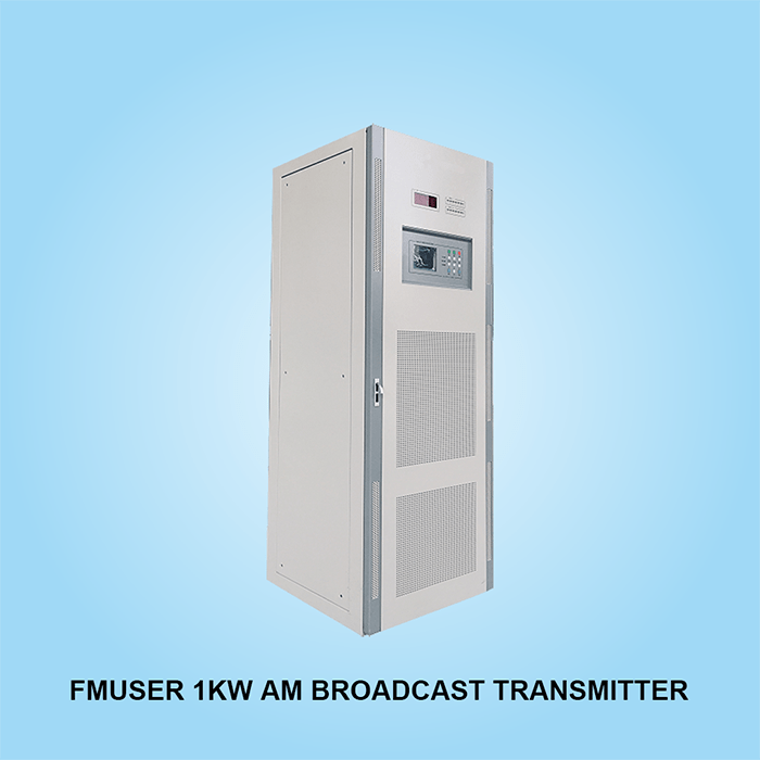
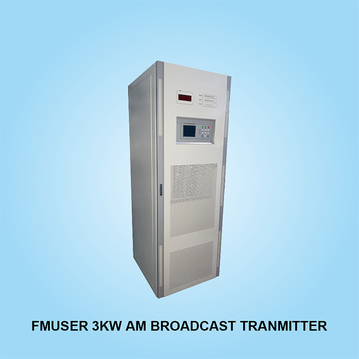
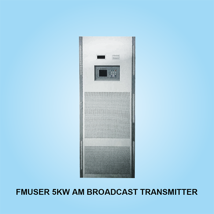
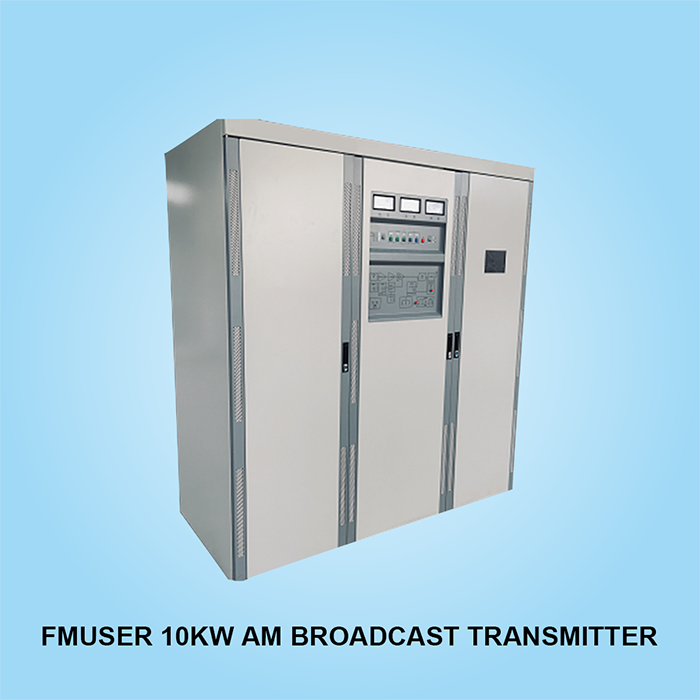
| 1KW AM Transmitter | 3KW AM Transmitter | 5KW AM Transmitter | 10KW AM Transmitter |
 |
 |
 |
 |
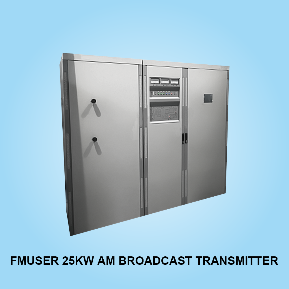
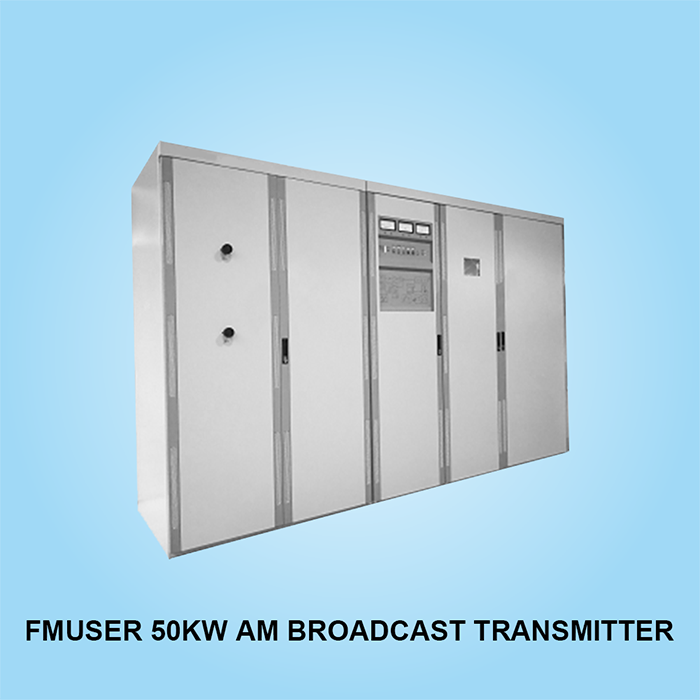
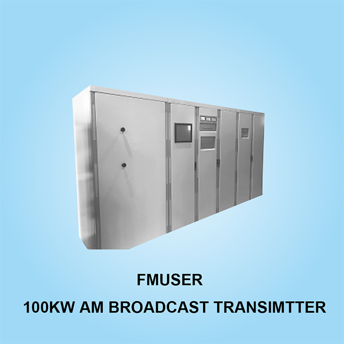
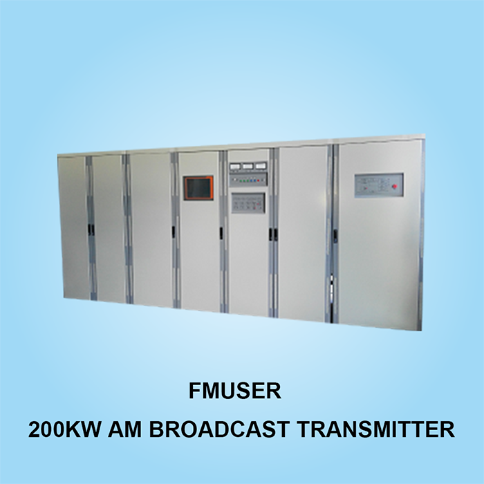
| 25KW AM Transmitter | 50KW AM Transmitter | 100KW AM Transmitter | 200KW AM Transmitter |
Since 2002, with its complete AM radio turnkey solutions, FMUSER Broadcast has so far successfully provided thoundsands of AM radio stations around the world with affordable AM broadcast products. We coverd several AM broadcasts transmitter with up to 200KW output power, professional AM test dummy loads, AM test bench and impedance matching unit. These reliable AM radio station equipment are designed as cost-effective broadcast solution for every broadcaster, aiming to improve their broadcast quality and reducing the cost of building a new AM broadcast station or equipment replacement.
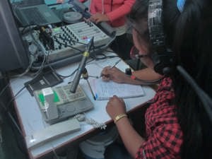
Watch our 10kW AM transmitter on-site construction video series in Cabanatuan, Philippines:
As a professional AM broadcasting equipment supplier, with its outstanding cost advantages and product performance, we have delivered industry-leading AM broadcasting solutions to dozens of large AM stations around the world.
Solid State AM Transmitters from 1KW, 3KW, 5KW, 10KW, 25KW, 50KW, 100KW to 200KW
FMUSER's high-power solid-state AM transmitters combine industry-leading broadcast performance with a low-cost design. All AM transmitters are equipped with touch screen and remote access control system so as to make sure every broadcaster can remotely control their transmitters in real. A reliable output matching network allows the transmitter to be tuned and maximized efficiency to suit various broadcast content.
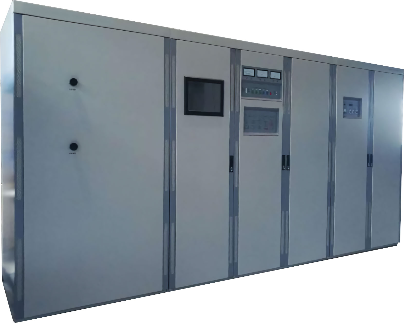
#1 Complete All-in-one Design: The compact model design of this series of AM transmitters makes efficient modular maintenance and quick response functions a reality. The built-in backup exciter will automatically turn on after a fault occurs, providing RF carrier to the power module and controlling signal modulation. With these professional AM transmitters from the Chinese supplier FMUSER, you will be more flexible and efficient to use the limited radio layout space to improve the overall operating efficiency of the radio.
#2 Built-in Meter System: Get an automatic impedance measurement system including automatic impedance, voltage, current, and power techniques, as well as a built-in directional coupler for spectrum measurements—raised to actual antenna loads to help you of engineers measure adjacent channel emissions.
#3 Reliable Circuit Design System: Using a unique circuit to dynamically stabilize the power supply, prevent AC line voltage changes, automatically restore the previous operating state after AC power failure, overvoltage or RF overload, and obtain fast and simple frequency change capability without special tools or external test equipment.
| Compact and modular design allows easy access to all of the component | 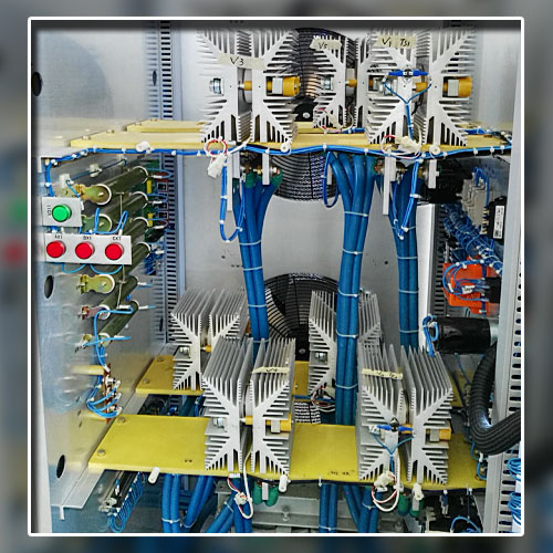 |
FMUSER AM transmitters were designed to make use of limited internal wiring space to the extreme - this saves the already expensive equipment production cost. The highly redundant, hot-swappable architecture integrates solid-state components, which will help your AM station deliver high-quality broadcasts consistently and efficiently and directly reduce your station operating costs.
The all-in-one air-cooling system not only offers this series an overall output efficiency of more than 72%, but also ensures its environmental friendliness, directly or indirectly reducing a lot of carbon emissions, you no longer need to getting over-worried about whether monthly electricity bills is too expensive.
In addition to several ultra-high power AM transmitters that can be delivered at any time, you will also acquire various auxiliaries to operate with the main system at the same time, including test loads with power up to 100kW/200kW (1, 3, 10kW also available), high-qualty test stands, and antenna impedance matching systems.
Choosing FMUSER's AM broadcasting solution means that you can still build a complete set of high-performance AM broadcasting system at a limited cost - which ensures the quality, long life and reliability of your broadacst station.
KEY FEATURES
-
-
-
-
-
-
-
-
- Resistive Loads
- RF Loads (see Catalogue)
- CW loads for powers up to MW range
- Pulse modulator loads for extreme peak powers
- RF matrix switches (coaxial/symmetrical)
- Baluns and feeder lines
- High Voltage Cables
- Auxiliary control/monitoring systems
- Redundant safety systems
- Additional interfacing options upon request
- Module Test Stands
- Tools and Special Equipment
-
-
-
-
-
-
-
Solid-state AM Transmitter Test Loads
Many FMUSER RF amplifiers, transmitters, power supplies or modulators operate at extremely high peak- and average-powers. This means that it is not possible to test such systems with their intended loads without risk of damaging the load. Plus, with such high output power, the medium wave transmitters are required to be maintained or tested every other period of time, thus a test load of high qualirt is a must for the broadcast station. The test loads manufactured by FMUSER have integrated every necessary components into all-in-one cabinet, which allows remote control and automatic&manual switching — truly, this could means a lot for any AM broadcast system management.
 |
 |
 |
| 1, 3, 10KW AM test load | 100KW AM transmitter test load | 200KW AM transmitter test load |
FMUSER's AM Module Test Stands
The test stands are mainly designed to ensure whether the AM transmitters are in good working conditions after the repairment of the buffer amplfier and power amplifier board. Once passing the test, the transmitter can be operated well — this helps to reduce the failure rate and suspension rate.

FMUSER's AM Antenna Tuning Unit
For AM transmitter antennas, the changable climates such as thundering, raining and humidity, etc. are the key factors to cause impedance deviation (50 Ω for example), that's exactly why an impedance matching system is needed — to re-match the antenna impedance. AM broadcast antennas are often quite large in size and quite easy to impedace deviation, and FMUSER's contactless impedance system are designed to the adaptive impedance adjustment of the AM broadcast antennas. Once the AM antenna impedance deviates by 50 Ω, the adaptive system will be adjusted to rematch the impedance of the modulation network to 50 Ω, so as to ensure the best transmission quality of your AM transmitter.

- How to choose the best AM Broadcast Transmitter?
- When choosing the best AM Broadcast Transmitter for an AM radio station, there are several factors to consider. First, you need to consider the power output of the transmitter, as this will determine the signal range. You should also consider the type of modulation the transmitter supports, as this will determine the quality of sound output. Additionally, consider the cost of the transmitter and the total cost of ownership such as maintenance, parts, and installation costs. Lastly, consider the customer service and after-sales service available from the manufacturer.
- How far can an AM broadcast transmitter cover?
- The most common output power for AM broadcast transmitters range from 500 watts to 50,000 watts. The range of coverage depends on the type of antenna used, and can range from several miles to several hundred miles.
- What determines the coverage of AM Broadcast Transmitter and why?
- The coverage of an AM Broadcast Transmitter is determined by its power output, antenna height, and antenna gain. The higher the power output, the greater the coverage area. Similarly, the higher the antenna height, the further the transmitter's signal can reach. Antenna gain also increases the transmitter's coverage area, as it focuses the signal in a specific direction.
- What types of radio station antenna are used for AM Broadcast Transmitter?
- Medium Wave (MW) Transmitter: A medium wave transmitter is a type of radio transmitter that uses medium frequency (MF) waves in the range of 500 kHz to 1.7 MHz. These signals can travel further than shortwave signals and can be used to broadcast local, regional, or international radio broadcasts. Medium wave signals can be heard on AM radios and are commonly used for news, talk shows, and music.
Shortwave (SW) Transmitter: A shortwave transmitter is a type of radio transmitter that uses shortwave frequencies in the range of 3-30 MHz. These signals can travel further than medium wave signals and can be used to broadcast international radio broadcasts. Shortwave signals can be heard on shortwave radios and are commonly used for international news and music.
Longwave (LW) Transmitter: A longwave transmitter is a type of radio transmitter that uses longwave frequencies in the range of 150-285 kHz. These signals can travel further than shortwave and medium wave signals and can be used to broadcast international radio broadcasts. Longwave signals can be heard on longwave radios and are commonly used for international news and music.
Choosing between these transmitters depends on the type of broadcast you are trying to send. Medium wave is best for local and regional broadcasts, shortwave is best for international broadcasts, and longwave is best for very long distance international broadcasts.
The main differences between the three transmitters are the frequency ranges they use and the distance that the signals can travel. Medium wave signals can travel up to 1,500 kilometers (930 miles), shortwave signals can travel up to 8,000 kilometers (5,000 miles), and longwave signals can travel up to 10,000 kilometers (6,200 miles). Additionally, medium wave signals are the weakest and most prone to interference, while longwave signals are the strongest and least prone to interference.
- What is medium wave transmitter, shortwave transmitter, and longwave transmitter?
- Medium Wave (MW) Transmitter: A medium wave transmitter is a type of radio transmitter that uses medium frequency (MF) waves in the range of 500 kHz to 1.7 MHz. These signals can travel further than shortwave signals and can be used to broadcast local, regional, or international radio broadcasts. Medium wave signals can be heard on AM radios and are commonly used for news, talk shows, and music.
Shortwave (SW) Transmitter: A shortwave transmitter is a type of radio transmitter that uses shortwave frequencies in the range of 3-30 MHz. These signals can travel further than medium wave signals and can be used to broadcast international radio broadcasts. Shortwave signals can be heard on shortwave radios and are commonly used for international news and music.
Longwave (LW) Transmitter: A longwave transmitter is a type of radio transmitter that uses longwave frequencies in the range of 150-285 kHz. These signals can travel further than shortwave and medium wave signals and can be used to broadcast international radio broadcasts. Longwave signals can be heard on longwave radios and are commonly used for international news and music.
Choosing between these transmitters depends on the type of broadcast you are trying to send. Medium wave is best for local and regional broadcasts, shortwave is best for international broadcasts, and longwave is best for very long distance international broadcasts.
The main differences between the three transmitters are the frequency ranges they use and the distance that the signals can travel. Medium wave signals can travel up to 1,500 kilometers (930 miles), shortwave signals can travel up to 8,000 kilometers (5,000 miles), and longwave signals can travel up to 10,000 kilometers (6,200 miles). Additionally, medium wave signals are the weakest and most prone to interference, while longwave signals are the strongest and least prone to interference.
- What are the applications of AM Broadcast Transmitter?
- The most common applications of an AM Broadcast Transmitter are radio and television broadcasting. AM Broadcast Transmitters are used to send out audio signals as radio waves to be received by radios, televisions, and other devices. Other applications of an AM Broadcast Transmitter include sending wireless data, providing wireless communication, and sending out audio and video signals.
- How many types of AM Broadcast Transmitter are there?
- There are three main types of AM broadcast transmitters: low-power, medium-power, and high-power. Low-power transmitters are typically used for short-range broadcasts, and have a range of up to 6 miles. Medium-power transmitters have a range of up to 50 miles, and are used for medium-range broadcasts. High-power transmitters are used for long-range broadcasts, and have a range of up to 200 miles. The main difference between these transmitters is the amount of power they produce, and the range they can cover.
- How to connect an AM Broadcast Transmitter?
- 1. Ensure that the transmitter is properly grounded and all safety regulations are followed.
2. Connect the audio source to the transmitter. This can be done through an audio mixer, a CD player, or any other audio source.
3. Connect the antenna to the transmitter. The antenna should be designed for AM broadcast frequencies and positioned for optimal signal quality.
4. Make sure that all cables and connectors are secure and in good condition.
5. Connect the transmitter to the power source, and turn it on.
6. Adjust the transmitter power level to the desired level, as indicated by the manufacturer’s instructions.
7. Tune the transmitter to the desired frequency.
8. Monitor the signal strength and quality with a signal meter to ensure it meets all regulations.
9. Test the broadcast signal and make any necessary adjustments.
- What else equipment do I need to start a complete AM radio station?
- To start a complete AM radio station, you will need an antenna, a power supply, a modulation monitor, an audio processor, a generator, a transmitter output filter, and a studio-transmitter link.
- What are the most important specifications of AM Broadcast Transmitter ?
- The most important physical and RF specifications of an AM Broadcast Transmitter are:
Physical:
-Power output
-Modulation index
-Frequency stability
-Operating temperature range
-Antenna type
RF:
-Frequency range
-Emission type
-Channel spacing
-Bandwidth
-Spurious emission levels
- How to maintain an AM radio station?
- To perform daily maintenance of an AM broadcast transmitter in an AM radio station, an engineer should begin by performing a visual inspection of the equipment. This includes making sure all connections are secure and looking for any signs of physical damage. The engineer should also check the RF output levels to ensure they adhere to FCC regulations. Additionally, the engineer should check the modulation levels, frequency accuracy, and audio levels for any audio processing equipment. The engineer should also inspect the antenna system, including the connections and grounding. Finally, the engineer should test any backup systems and make sure the transmitter is properly cooled.
- How to repair a AM Broadcast Transmitter if it fail working?
- Repairing a AM broadcast transmitter and replacing broken parts will require knowledge of electronics and access to the right tools and replacement parts. The first step is to locate the source of the problem. This can be done through visually inspecting for damaged or broken components, or running diagnostic tests if the exact fault is not immediately apparent. Once the source of the problem is known, the next step is to replace the broken parts, if necessary. Depending on the type of transmitter, this may involve soldering new components onto the circuit board, or unscrewing and replacing physical parts. Once the new parts are installed, the transmitter should be tested to ensure that it is functioning properly.
- What is the basic structure of AM Broadcast Transmitter?
- The basic structure of an AM Broadcast Transmitter consists of an oscillator, a modulator, an amplifier, an antenna, and a power supply. The oscillator generates the radio signal, the modulator modulates the signal with audio information, the amplifier increases the signal strength, the antenna radiates the signal, and the power supply supplies the necessary power for the device to function. The oscillator is the most important structure in determining the attributes and performance of an AM Broadcast Transmitter, as it determines the frequency of the signal. Without the oscillator, an AM Broadcast Transmitter would not be able to work normally.
- How are you?
- I am fine
- Limitations of Amplitude Modulation
-
1. Low Efficiency - Since the useful power that lies in the small bands is quite small, so the efficiency of AM system is low.
2. Limited Operating Range – The range of operation is small due to low efficiency. Thus, transmission of signals is difficult.
3. Noise in Reception – As the radio receiver finds it difficult to distinguish between the amplitude variations that represent noise and those with the signals, heavy noise is prone to occur in its reception.
4. Poor Audio Quality – To obtain high fidelity reception, all audio frequencies till 15 KiloHertz must be reproduced and this necessitates the bandwidth of 10 KiloHertz to minimise the interference from the adjacent broadcasting stations. Therefore in AM broadcasting stations audio quality is known to be poor.
- Application & Uses of Amplitude Modulation
-
1. Radio broadcastings
2. TV broadcastings
3. Garage door opens keyless remotes
4. Transmits TV signals
5. Short wave radio communications
6. Two way radio communication
- Comparision of Various AM
-
VSB-SC
1. Definition - A vestigial sideband (in radio communication)is a sideband that has been only partly cut off or suppressed.
2. Application - TV broadcastings & Radio broadcastings
3. Uses - Transmits TV signals
SSB-SC
1. Definition - Single-sidebandmodulation (SSB) is a refinement of amplitude modulation that more efficiently uses electrical power and bandwidth
2. Application - TV broadcastings & Shortwave Radio broadcastings
3. Uses - Shortwave radio communications
DSB-SC
1. Definition - In radio communications, aside band is a band of frequencies hig her than or lower than the carrier frequency, containing power as a result of the modulation process.
2. Application - TV broadcastings & Radio broadcastings
3. Uses - 2-way radio communications
PARAMETER
VSB-SC
SSB-SC
DSB-SC
Definition
A vestigial sideband (in radio communication)is a sideband that has been only partly cut off or suppressed.
Single-sidebandmodulation (SSB) is a refinement of amplitude modulation that more efficiently uses electrical power and bandwidth
In radio communications, aside band is a band of frequencies hig her than or lower than the carrier frequency, containing power as a result of the modulation process.
Application
TV broadcastings & Radio broadcastings
TV broadcastings & Shortwave Radio broadcastings
TV broadcastings & Radio broadcastings
Uses
Transmits TV signals
Shortwave radio communications
2-way radio communications
- A Complete Guide to Amplitude Modulations (AM)
-
What is Amplitude Modulation (AM)?
- "Modulation is the process of superimposing a low frequency signal on a high frequency carrier signal."
- "The process of modulation can be defined as varying the RF carrier wave in accordance with the intelligence or information in a low frequency signal."
- "Modulation is defined as the precess by which some characteristics, usually amplitude, frequency or phase, of a carrier is varied in accordance with instantaneous value of some other voltage, called the modulating voltage."
Why Modulation is Needed?
1. If two musical programs were played at the same time within distance, it would be difficult for anyone to listen to one source and not hear the second source. Since all musical sounds have approximately the same frequency range, form about 50 Hz to 10KHz. If a desired program is shifted up to a band of frequencies between 100KHz and 110KHz, and the second program shifted up to the band between 120KHz and 130KHz, Then both programs gave still 10KHz bandwidth and the listener can (by band selection) retrieve the program of his own choice. The receiver would down shift only the selected band of frequencies to a suitable range of 50Hz to 10KHz.
2. A second more technical reason to shift the message signal to a higher frequency is related to antenna size. It is to be noted that the antenna size is inversely proportional to the frequency to be radiated. This is 75 meters at 1 MHz but at 15KHz it has increased to 5000 meters (or just over 16,000 feet) a vertical antenna of this size is impossible.
3. The third reason for modulating a high frequency carrier is that RF (radio frequency) energy will travel a great distance than the same amount of energy transmitted as sound power.
Types of Modulation
The carrier signal is a sine wave at the carrier frequency. Below equation shows that the sine wave has three characteristics that can be altered.
Instantaneous voltage (E) =Ec(max)Sin(2πfct + θ)
The term that may be varied are the carrier voltage Ec, the carrier frequency fc, and the carrier phase angle θ. So three forms of modulations are possible.
1. Amplitude Modulation
Amplitude modulation is an increase or decrease of the carrier voltage (Ec), will all other factors remaining constant.
2. Frequency Modulation
Frequency modulation is a change in the carrier frequency (fc) with all other factors remaining constant.
3. Phase Modulation
Phase modulation is a change in the carrier phase angle (θ). The phase angle cannot change without also affecting a change in frequency. Therefore, phase modulation is in reality a second form of frequency modulation.
EXPLAINATION OF AM
The method of varying amplitude of a high frequency carrier wave in accordance with the information to be transmitted, keeping the frequency and phase of the carrier wave unchanged is called Amplitude Modulation. The information is considered as the modulating signal and it is superimposed on the carrier wave by applying both of them to the modulator. The detailed diagram showing the amplitude modulation process is given below.
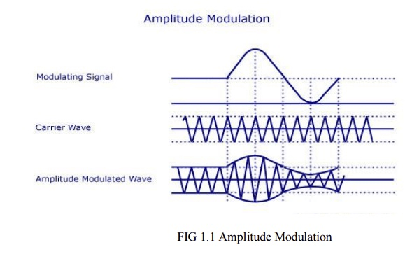
As shown above, the carrier wave has positive and negative half cycles. Both these cycles are varied according to the information to be sent. The carrier then consists of sine waves whose amplitudes follow the amplitude variations of the modulating wave. The carrier is kept in an envelope formed by the modulating wave. From the figure, you can also see that the amplitude variation of the high frequency carrier is at the signal frequency and the frequency of the carrier wave is the same as the frequency of the resulting wave.
Analysis of Amplitude Modulation Carrier Wave
Let vc = Vc Sin wct
vm = Vm Sin wmt
vc – Instantaneous value of the carrier
Vc – Peak value of the carrier
Wc – Angular velocity of the carrier
vm – Instantaneous value of the modulating signal
Vm – Maximum value of the modulating signal
wm – Angular velocity of the modulating signal
fm – Modulating signal frequency
It must be noted that the phase angle remains constant in this process. Thus it can be ignored.
It must be noted that the phase angle remains constant in this process. Thus it can be ignored.
The amplitude of the carrier wave varies at fm.The amplitude modulated wave is given by the equation A = Vc + vm = Vc + Vm Sin wmt
= Vc [1+ (Vm/Vc Sin wmt)]
= Vc (1 + mSin wmt)
m – Modulation Index. The ratio of Vm/Vc.
Instantaneous value of amplitude modulated wave is given by the equation v = A Sin wct = Vc (1 + m Sin wmt) Sin wct
= Vc Sin wct + mVc (Sin wmt Sin wct)
v = Vc Sin wct + [mVc/2 Cos (wc-wm)t – mVc/2 Cos (wc + wm)t]
The above equation represents the sum of three sine waves. One with amplitude of Vc and a frequency of wc/2 , the second one with an amplitude of mVc/2 and frequency of (wc – wm)/2 and the third one with an amplitude of mVc/2 and a frequency of (wc + wm)/2 .
In practice the angular velocity of the carrier is known to be greater than the angular velocity of the modulating signal (wc >> wm). Thus, the second and third cosine equations are more close to the carrier frequency. The equation is represented graphically as shown below.
Frequency Spectrum of AM Wave
Lower side frequency – (wc – wm)/2
Upper side frequency – (wc +wm)/2
The frequency components present in the AM wave are represented by vertical lines approximately located along the frequency axis. The height of each vertical line is drawn in proportion to its amplitude. Since the angular velocity of the carrier is greater than the angular velocity of the modulating signal, the amplitude of side band frequencies can never exceed half of the carrier amplitude.
Thus there will not be any change in the original frequency, but the side band frequencies (wc – wm)/2 and (wc +wm)/2 will be changed. The former is called the upper side band (USB) frequency and the later is known as lower side band (LSB) frequency.
Since the signal frequency wm/2 is present in the side bands, it is clear that the carrier voltage component does not transmit any information.
Two side banded frequencies will be produced when a carrier is amplitude modulated by a single frequency. That is, an AM wave has a band width from (wc – wm)/2 to (wc +wm)/2 , that is, 2wm/2 or twice the signal frequency is produced. When a modulating signal has more than one frequency, two side band frequencies are produced by every frequency. Similarly for two frequencies of the modulating signal 2 LSB‘s and 2 USB‘s frequencies will be produced.
The side bands of frequencies present above the carrier frequency will be same as the ones present below. The side band frequencies present above the carrier frequency is known to be the upper side band and all those below the carrier frequency belong to the lower side band. The USB frequencies represent the some of the individual modulating frequencies and the LSB frequencies represent the difference between the modulating frequency and the carrier frequency. The total bandwidth is represented in terms of the higher modulating frequency and is equal to twice this frequency.
Modulation Index (m)
The ratio between the amplitude change of carrier wave to the amplitude of the normal carrier wave is called modulation index. It is represented by the letter ‗m‘.
It can also be defined as the range in which the amplitude of the carrier wave is varied by the modulating signal. m = Vm/Vc.
Percentage modulation, %m = m*100 = Vm/Vc * 100
The percentage modulation lies between 0 and 80%.
Another way of expressing the modulation index is in terms of the maximum and minimum values of the amplitude of the modulated carrier wave. This is shown in the figure below.
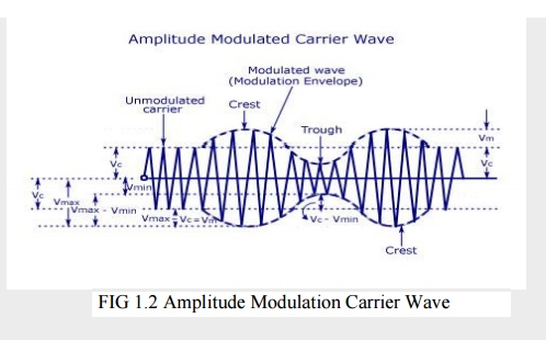
2 Vin = Vmax – Vmin
Vin = (Vmax – Vmin)/2
Vc = Vmax – Vin
= Vmax – (Vmax-Vmin)/2 =(Vmax + Vmin)/2
Substituting the values of Vm and Vc in the equation m = Vm/Vc , we get
M = Vmax – Vmin/Vmax + Vmin
As told earlier, the value of ‗m‘ lies between 0 and 0.8. The value of m determines the strength and the quality of the transmitted signal. In an AM wave, the signal is contained in the variations of the carrier amplitude. The audio signal transmitted will be weak if the carrier wave is only modulated to a very small degree. But if the value of m exceeds unity, the transmitter output produces erroneous distortion.
Power Relations in an AM wave
A modulated wave has more power than had by the carrier wave before modulating. The total power components in amplitude modulation can be written as:
Ptotal = Pcarrier + PLSB + PUSB
Considering additional resistance like antenna resistance R.
Pcarrier = [(Vc/√2)/R]2 = V2C/2R
Each side band has a value of m/2 Vc and r.m.s value of mVc/2√2. Hence power in LSB and USB can be written as
PLSB = PUSB = (mVc/2√2)2/R = m2/4*V2C/2R = m2/4 Pcarrier
Ptotal = V2C/2R + [m2/4*V2C/2R] + [m2/4*V2C/2R] = V2C/2R (1 + m2/2) = Pcarrier (1 + m2/2)
In some applications, the carrier is simultaneously modulated by several sinusoidal modulating signals. In such a case, the total modulation index is given as
Mt = √(m12 + m22 + m32 + m42 + …..
If Ic and It are the r.m.s values of unmodulated current and total modulated current and R is the resistance through which these current flow, then
Ptotal/Pcarrier = (It.R/Ic.R)2 = (It/Ic)2
Ptotal/Pcarrier = (1 + m2/2)
It/Ic = 1 + m2/2
- Amplitude Modulation (AM) FAQ
-
1. Define modulation?
Modulation is a process by which some characteristics of high frequency carrier signal is varied in accordance with the instantaneous value of the modulating signal.
2. What are the types of analog modulation?
Amplitude modulation.
Angle Modulation
Frequency modulation
Phase modulation.
3. Define depth of modulation.
It is defined as the ratio between message amplitude to that of carrier amplitude. m=Em/Ec
4. What are the degrees of modulation?
Under modulation. m<1
Critical modulation m=1
Over modulation m>1
5. What is the need for modulation?
- Needs for modulation:
- Ease of transmission
- Multiplexing
- Reduced noise
- Narrow bandwidth
- Frequency assignment
- Reduce the equipments limitations
6. What are the types of AM modulators?
There are two types of AM modulators. They are
- Linear modulators
- Non-linear modulators
Linear modulators are classified as follows
- Transistor modulator
There are three types of transistor modulator.
- Collector modulator
- Emitter modulator
- Base modulator
- Switching modulators
Non-linear modulators are classified as follows
- Square law modulator
- Product modulator
- Balanced modulator
7. What is the difference between high level and low level modulation?
In high level modulation, the modulator amplifier operates at high power levels and delivers power directly to the antenna. In low level modulation, the modulator amplifier performs modulation at relatively low power levels. The modulated signal is then amplified to high power level by class B power amplifier. The amplifier feeds power to antenna.
8. Define Detection (or) Demodulation.
Detection is the process of extracting modulating signal from the modulated carrier. Different types of detectors are used for different types of modulations.
9. Define Amplitude Modulation.
In amplitude modulation, the amplitude of a carrier signal is varied according to variations in amplitude of modulating signal.
The AM signal can be represented mathematically as, eAM = (Ec + Em sinωmt ) sinωct and the modulation index is given as,m = Em /EC (or) Vm/Vc
10. What is Super Heterodyne Receiver?
The super heterodyne receiver converts all incoming RF frequencies to a fixed lower frequency, called intermediate frequency (IF). This IF is then amplitude and detected to get the original signal.
11. What is single tone and multi tone modulation?
- If modulation is performed for a message signal with more than one frequency component then the modulation is called multi tone modulation.
- If modulation is performed for a message signal with one frequency component then the modulation is called single tone modulation.
12. Compare AM with DSB-SC and SSB-SC.
S.No
AM signal
DSB-SC
SSB-SC
1
Bandwidth 2fm
Bandwidth 2fm
Bandwidth fm
2
Contains USB,LSB,Carrier
Contains USB.LSB
USB.LSB
3
More Power is required for transmission
Power required is less than that of AM
Power required is less than AM &DSB-SC
13. What are the advantages of VSB-AM?
- It has bandwidth greater than SSB but less than DSB system.
- Power transmission greater than DSB but less than SSB system.
- No low frequency component lost. Hence it avoids phase distortion.
14. How will you generating DSBSC-AM?
There are two ways of generating DSBSC-AM such as
- Balanced modulator
- Ring modulators.
15. What are advantages of ring modulator?
- Its output is stable.
- It requires no external power source to activate the diodes. c).Virtually no maintenance.
- Long life.
16. Define Demodulation.
Demodulation or detection is the process by which modulating voltage is recovered from the modulated signal. It is the reverse process of modulation. The devices used for demodulation or detection are called demodulators or detectors. For amplitude modulation, detectors or demodulators are categorized as:
- Square-law detectors
- Envelope detectors
17. Define Multiplexing.
Multiplexing is defined as the process of transmitting several message signals Simultaneously over a single channel.
18. Define Frequency Division Multiplexing.
Frequency division multiplexing is defined as many signals are transmitted simultaneously with each signal occupying a different frequency slot within a common bandwidth.
19. Define Guard Band.
Guard Bands are introduced in the spectrum of FDM in order to avoid any interference between the adjacent channels. Wider the guard bands, Smaller the interference.
20. Define SSB-SC.
- SSB-SC stands for Single Side Band Suppressed Carrier
- When only one sideband is transmitted, the modulation is referred to as Single side band modulation. It is also called as SSB or SSB-SC.
21. Define DSB-SC.
After modulation, the process of transmitting the sidebands (USB, LSB) alone and suppressing the carrier is called as Double Side Band-Suppressed Carrier.
22. What are the disadvantages of DSB-FC?
- Power wastage takes place in DSB-FC
- DSB-FC is bandwidth inefficient system.
23. Define Coherent Detection.
During Demodulation carrier is exactly coherent or synchronized in both the frequency and phase, with the original carrier wave used to generate the DSB-SC wave.
This method of detection is called as coherent detection or synchronous detection.
24. What is Vestigial Side Band Modulation?
Vestigial Sideband Modulation is defined as a modulation in which one of the sideband is partially suppressed and the vestige of the other sideband is transmitted to compensate for that suppression.
25. What are the advantages of signal sideband transmission?
- Power consumption
- Bandwidth conservation
- Noise reduction
26. What are the disadvantages of single side band transmission?
- Complex receivers: Single side band systems require more complex and expensive receivers thn conventiaonal AM transmission.
- Tuning difficulties: Single side band receivers require more complex and precise tunig than conventional AM receivers.
27. Compare linear and non-linear modulators?
Linear Modulators
- Heavy filtering is not required.
- These modulators are used in high level modulation.
- The carrier voltage is very much greater than modulating signal voltage.
Non Linear Modulators
- Heavy filtering is required.
- These modulators are used in low level modulation.
- The modulating signal voltage is very much greater than the carrier signal voltage.
28. What is frequency translation?
Suppose that a signal is band limited to the frequency range extending from a frequency f1 to a frequency f2. The process of frequency translation is one in which the original signal is replaced with a new signal whose spectral range extends from f1‘ and f2‘ and which new signal bears, in recoverable form the same information as was borne by the original signal.
29. What are the two situations identified in frequency translations?
- Up Conversion: In this case the translated carrier frequency is greater than the incoming carrier
- Down Conversion: In this case the translated carrier frequency is smaller than the increasing carrier frequency.
Thus, a narrowband FM signal requires essentially the same transmission bandwidth as the AM signal.
30. What is BW for AM wave?
The difference between these two extreme frequencies is equal to the bandwidth of the AM wave.
Therefore, Bandwidth, B = (fc + fm) - (fc - fm) B = 2fm
31. What is the BW of DSB-SC signal?
Bandwidth, B = (fc + fm) - (fc - fm) B = 2f
It is obvious that the bandwidth of DSB-SC modulation is same as that of general AM waves.
32. What are the demodulation methods for DSB-SC signals?
The DSB-SC signal may be demodulated by following two methods:
- Synchronous detection method.
- Using envelope detector after carrier reinsertion.
33. Write the applications of Hilbert transform?
- For generation of SSB signals,
- For designing of minimum phase type filters,
- For representation of band pass signals.
34. What are the methods for generating SSB-SC signal?
SSB-SC signals may be generated by two methods as under:
- Frequency discrimination method or filter method.
- Phase discrimination method or phase-shift method.
GLOSSARY TERMS
1. Amplitude modulation: The modulation of a wave by varying its amplitude, used especially as a means of broadcasting an audio signal by combining it with a radio carrier wave.
2. The modulation index: (modulation depth) of a modulation scheme describes by how much the modulated variable of the carrier signal varies around its unmodulated level.
3. Narrowband FM: If the modulation index of FM is kept under 1, then the FM produced is regarded as narrow band FM.
4. Frequency modulation (FM): the encoding of information in a carrier wave by varying the instantaneous frequency of the wave.
5. Amplication: The level is carefully chosen so that it does not overload the mixer when strong signals are present, but enables the signals to be amplified sufficiently to ensure a good signal to noise ratio is achieved.
6. Modulation: The process by which some of the characteristics of carrier wave is varied in accordance with the message signal.
- What is the difference between SW, MW and FM radio?
-
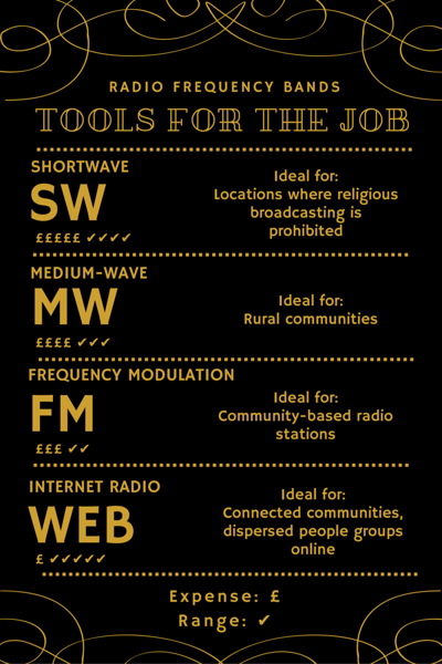
Shortwave (SW)
Shortwave radio has a huge range – it can be received thousands of miles from the transmitter, and transmissions can cross oceans and mountain ranges. This makes it ideal for reaching nations without a radio network or where Christian broadcasting is prohibited. Put simply, shortwave radio overcomes boundaries, whether geographical or political. SW transmissions are easy to receive, too: even cheap, simple radios are able to pick up a signal.
The strengths of shortwave radio make it well suited for Feba's key focus area of the Persecuted Church. For example, in areas of North East Africa where religious broadcasting is banned inside the country, our local partners can create audio content, send it out of the country and have it beamed back in via a SW transmission without risk of prosecution.
Yemen is currently experiencing a severe and violent crisis with the conflict causing a massive humanitarian emergency. As well as providing spiritual encouragement, our partners broadcast material addressing current social, health and wellbeing issues from a Christian perspective.
In a country where Christians make up just 0.08% of the population and experience persecution because of their faith, Reality Church is a weekly 30 minute shortwave radio feature that supports Yemeni believers in local dialect. Listeners can access supportive radio broadcasts in private and anonymously.
A powerful way to reach marginalised communities across borders, shortwave is highly effective at reaching a remote audience with the Gospel and, in areas where Christians are persecuted, leaves listeners and broadcasters free from fear of reprisal.
Medium-wave (MW)
Medium-wave radio is generally used for local broadcasts and is perfect for rural communities. With a medium transmission range, it can reach isolated areas with a strong, reliable signal. Medium-wave transmissions can be broadcast through established radio networks - where these networks exist.

In northern India, local cultural beliefs leave women marginalised and many are confined to their homes. To women in this position, transmissions from Feba North India (using an established radio network) are a crucial link with the outside world. Its values-based programming provides education, healthcare guidance and input on women’s rights, prompting conversations around spirituality with women who contact the station. In this context, radio is bringing a message of hope and empowerment to women listening at home.
Frequency Modulation (FM)
For a community-based radio station, FM is king!

Radio Umoja FM in the DRC recently launched, aiming to give the community a voice. FM provides a short-range signal - generally to anywhere within sight of the transmitter, with excellent sound quality. It can typically cover the area of a small city or large town - making it perfect for a radio station focusing on a limited geographical area speaking into local issues. While shortwave and medium-wave stations can be expensive to operate, a license for a community-based FM station is much cheaper.
Afno FM, Feba’s partner in Nepal, provides vital healthcare advice to the local communities in Okhaldhunga and Dadeldhura. Using FM allows them to put across important information, perfectly clearly, to targeted areas. In rural Nepal, there is widespread suspicion of hospitals and some common medical conditions are seen as taboo. There is a very real need for well-informed, non-judgmental health advice and Afno FM helps meet this need. The team work in partnership with local hospitals to prevent and treat common health problems (particularly those with a stigma attached to them)and to address local people’s fear of healthcare professionals, encouraging listeners to seek hospital treatment when they need it. FM is also used in radio for emergency response - with a 20kg FM transmitter being light enough to carry to disaster affected communities as part of an easy to transport suitcase studio.
Internet Radio
The rapid development of web-based technology offers huge opportunities for radio broadcasting. Internet-based stations are quick and easy to set up (sometimes taking as little as a week to get up and running! It can cost a lot less than regular transmissions.

And because the internet has no borders, a web-based radio audience can have global reach. One drawback is that Internet radio is reliant on Internet coverage and the listener’s access to a computer or smartphone.
In a global population of 7.2 billion, three-fifths, or 4.2 billion people, still do not have regular access to the Internet. Internet based community radio projects are therefore not currently suitable for some of the poorest and most inaccessible areas of the world.
- What is SW and MW?
- The name "shortwave" originated during the beginning of radio in the early 20th century, when the radio spectrum was divided into long wave (LW), medium wave (MW), and short wave (SW) bands based on the length of the wave.
- Is AM and MW the same?
- AM, which stands for Amplitude Modulation (AM) is the oldest radio broadcasting system in the UK. The term AM is commonly used to cover both Medium Wave (MW) and Long Wave (LW).
- What is the difference between shortwave and medium wave?
- By one or more reflections between the earth and the ionosphere, a short-wave radio signal can be received at long distances from the transmitter. And medium wave or mediumwave (MW) is a part of the Medium frequency (MF) radio band used for AM broadcasting.
- Is AM radio shortwave?
- It's called shortwave because, quite literally, the waves emitted are short as opposed to long wave and medium wave, used by AM radio, and wideband VHF (very high frequency) used by FM radio. These short waves can travel thousands of miles across the globe, so shortwave radio is, by nature, international.
- Is AM radio the same as medium wave?
- Medium wave (MW) signals are transmitted using amplitude modulation (AM) and the terms are used interchangeably. FM signals are mostly transmitted in the very high frequency (VHF) or ultra high frequency (UHF) bands and are used for voice (radio) as well as video (TV) broadcasting.
- What is the frequency range of AM?
- The AM band in the United States covers frequencies from 540 kHz up to 1700 kHz, in 10 kHz steps (540, 550, 560 ... 1680, 1690, 1700). 530 kHz in the United States is not available for broadcast use, but is reserved for the use of very low powered Travelers' Information Stations.
- Why is AM radio still used?
-
Amplitude modulation (AM) is by far the oldest form of modulation known. The first broadcast stations were AM, but even earlier, CW or continuous-wave signals with Morse code were a form of AM. They’re what we call on-off keying (OOK) or amplitude-shift keying (ASK) today.
Even though AM is the first and oldest, it’s still around in more forms than you might think. AM is simple, low cost, and amazingly effective. Even though the demand for high-speed data has driven us toward orthogonal frequency-division multiplexing (OFDM) as the most spectrally efficient modulation scheme, AM is still involved in the form of quadrature amplitude modulation (QAM).
What made me think of AM? During the big winter storm of two months or so ago, I got most of my weather and emergency information from the local AM stations. Mainly from WOAI, the 50-kW station that’s been around for ages. I doubt they were still cranking out 50 kW during the power outage, but they were on the air during the whole weather event. Many if not most AM stations were up and running on backup power. Reliable and comforting.
There are over 6,000 AM stations in the U.S. today. And they still have a huge audience of listeners, typically locals who seek out the latest weather, traffic, and news information. Most still listen in their cars or trucks. There’s a wide range of talk radio shows and you can still hear a baseball or football game on AM. Music options have diminished, as they have mostly moved to FM. Yet, there are some country and Tejano music stations on AM. It all depends on the local audience, which is quite varied.
AM radio broadcasts in 10-kHz wide channels between 530 and 1710 kHz. All stations use towers, so polarization is vertical. During the day, propagation is mainly ground wave with a range of about 100 miles. For the most part, it depends on the power level, usually 5 kW or 1 kW. Not too many 50-kW stations exist, but their range is obviously farther.
At night, of course, the propagation changes as the ionized layers change and make signals travel farther thanks to their ability to be refracted by the upper ion layers to produce multiple signal hops at distances to a thousand miles or more. If you have a good AM radio and a long antenna you can listen to stations all over the country at night.
AM is also the main modulation of short-wave radio, which you can hear worldwide from 5 to 30 MHz. It’s still one of the main sources of information for many third-world countries. Short-wave listening also remains a popular hobby.
Besides broadcasting, where is AM still used? Ham radio still utilizes AM; not in the original high-level form, but as single sideband (SSB). SSB is AM with a suppressed carrier and one sideband filtered out, leaving a narrow 2,800-Hz channel of voice. It’s widely used and highly effective, especially in the ham bands from 3 to 30 MHz. The military and some marine radios continue to use some form of SSB, too.
But wait, that’s not all. AM still can be found in Citizen’s Band radios. Plain-old AM remains in the mix, as does SSB. Moreover, AM is the main modulation of aircraft radio used between planes and the tower. These radios operate in the 118- to 135-MHz band. Why AM? I’ve never figured that out, but it works fine.
Finally, AM is still with us in QAM form, the combination of phase and amplitude modulation. Most OFDM channels use one form of QAM to get the higher data rates they can deliver.
Anyway, AM isn’t dead yet, and in fact it seems to be Aging Majestically.
- What is AM Transmitter and How it Works?
-
What is AM Transmitter?
Transmitters that transmit AM signals are known as AM transmitters, it is also known as AM radio transmitter or AM broadcast transmitter, for they're used to tranmit radio signals from one side to the other.

These transmitters are used in medium wave (MW) and short wave (SW) frequency bands for AM broadcast.
The MW band has frequencies between 550 KHz and 1650 KHz, and the SW band has frequencies ranging from 3 MHz to 30 MHz. The two types of AM transmitters that are used based on their transmitting powers are:
- High Level
- Low Level
High level transmitters use high level modulation, and low level transmitters use low level modulation. The choice between the two modulation schemes depends on the transmitting power of the AM transmitter.
In broadcast transmitters, where the transmitting power may be of the order of kilowatts, high level modulation is employed. In low power transmitters, where only a few watts of transmitting power are required , low level modulation is used.
High-Level And Low-Level Transmitters
Below figure's show the block diagram of high-level and low-level transmitters. The basic difference between the two transmitters is the power amplification of the carrier and modulating signals.
Figure (a) shows the block diagram of high-level AM transmitter.
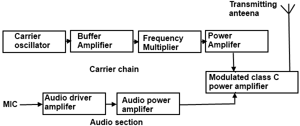
Figure (a) is drawn for audio transmission. In high-level transmission, the powers of the carrier and modulating signals are amplified before applying them to the modulator stage, as shown in figure (a). In low-level modulation, the powers of the two input signals of the modulator stage are not amplified. The required transmitting power is obtained from the last stage of the transmitter, the class C power amplifier.
The various sections of the figure (a) are:
- Carrier oscillator
- Buffer amplifier
- Frequency multiplier
- Power amplifier
- Audio chain
- Modulated class C power amplifier
Carrier Oscillator
The carrier oscillator generates the carrier signal, which lies in the RF range. The frequency of the carrier is always very high. Because it is very difficult to generate high frequencies with good frequency stability, the carrier oscillator generates a sub multiple with the required carrier frequency.
This sub multiple frequency is multiplied by the frequency multiplier stage to get the required carrier frequency.
Further, a crystal oscillator can be used in this stage to generate a low frequency carrier with the best frequency stability. The frequency multiplier stage then increases the frequency of the carrier to its required value.
Buffer Amplifier
The purpose of the buffer amplifier is two fold. It first matches the output impedance of the carrier oscillator with the input impedance of the frequency multiplier, the next stage of the carrier oscillator. It then isolates the carrier oscillator and frequency multiplier.
This is required so that the multiplier does not draw a large current from the carrier oscillator. If this occurs, the frequency of the carrier oscillator will not remain stable.
Frequency Multiplier
The sub-multiple frequency of the carrier signal, generated by the carrier oscillator , is now applied to the frequency multiplier through the buffer amplifier. This stage is also known as harmonic generator. The frequency multiplier generates higher harmonics of carrier oscillator frequency. The frequency multiplier is a tuned circuit that can be tuned to the requisite carrier frequency that is to be transmitted.
Power Amplifier
The power of the carrier signal is then amplified in the power amplifier stage. This is the basic requirement of a high-level transmitter. A class C power amplifier gives high power current pulses of the carrier signal at its output.
Audio Chain
The audio signal to be transmitted is obtained from the microphone, as shown in figure (a). The audio driver amplifier amplifies the voltage of this signal. This amplification is necessary to drive the audio power amplifier. Next, a class A or a class B power amplifier amplifies the power of the audio signal.
Modulated Class C Amplifier
This is the output stage of the transmitter. The modulating audio signal and the carrier signal, after power amplification, are applied to this modulating stage. The modulation takes place at this stage. The class C amplifier also amplifies the power of the AM signal to the reacquired transmitting power. This signal is finally passed to the antenna., which radiates the signal into space of transmission.
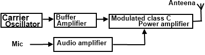
The low-level AM transmitter shown in the figure (b) is similar to a high-level transmitter, except that the powers of the carrier and audio signals are not amplified. These two signals are directly applied to the modulated class C power amplifier.
Modulation takes place at the stage, and the power of the modulated signal is amplified to the required transmitting power level. The transmitting antenna then transmits the signal.
Coupling Of Output Stage And Antenna
The output stage of the modulated class C power amplifier feeds the signal to the transmitting antenna.
To transfer maximum power from the output stage to the antenna it is necessary that the impedance of the two sections match. For this , a matching network is required.
The matching between the two should be perfect at all transmitting frequencies. As the matching is required at different frequencies, inductors and capacitors offering different impedance at different frequencies are used in the matching networks.
The matching network must be constructed using these passive components. This is shown in below Figure (c).
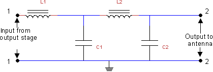
The matching network used for coupling the output stage of the transmitter and the antenna is called double π-network.
This network is shown in figure (c). It consists of two inductors , L1 and L2 and two capacitors, C1 and C2. The values of these components are chosen such that the input impedance of the network between 1 and 1'. Shown in figure (c) is matched with the output impedance of the output stage of the transmitter.
Further, the output impedance of the network is matched with the impedance of the antenna.
The double π matching network also filters unwanted frequency components appearing at the output of the last stage of the transmitter.
The output of the modulated class C power amplifier may contain higher harmonics, such as second and third harmonics, that are highly undesirable.
The frequency response of the matching network is set such that these unwanted higher harmonics are totally suppressed, and only the desired signal is coupled to the antenna.
- AM or FM Transmitter? Main Differences
-
The antenna present at the end of transmitter section, transmits the modulated wave. In this chapter, let us discuss about AM and FM transmitters.
AM Transmitter
AM transmitter takes the audio signal as an input and delivers amplitude modulated wave to the antenna as an output to be transmitted. The block diagram of AM transmitter is shown in the following figure.
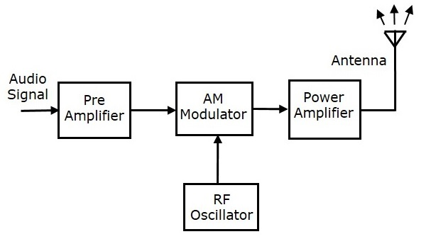
The working of AM transmitter can be explained as follows:
- The audio signal from the output of the microphone is sent to the pre-amplifier, which boosts the level of the modulating signal.
- The RF oscillator generates the carrier signal.
- Both the modulating and the carrier signal is sent to AM modulator.
- Power amplifier is used to increase the power levels of AM wave. This wave is finally passed to the antenna to be transmitted.
FM Transmitter
FM transmitter is the whole unit, which takes the audio signal as an input and delivers FM wave to the antenna as an output to be transmitted. The block diagram of FM transmitter is shown in the following figure.
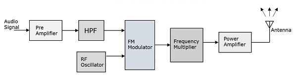
The working of FM transmitter can be explained as follows:
- The audio signal from the output of the microphone is sent to the pre-amplifier, which boosts the level of the modulating signal.
- This signal is then passed to high pass filter, which acts as a pre-emphasis network to filter out the noise and improve the signal to noise ratio.
- This signal is further passed to the FM modulator circuit.
- The oscillator circuit generates a high frequency carrier, which is sent to the modulator along with the modulating signal.
- Several stages of frequency multiplier are used to increase the operating frequency. Even then, the power of the signal is not enough to transmit. Hence, a RF power amplifier is used at the end to increase the power of the modulated signal. This FM modulated output is finally passed to the antenna to be transmitted.
- AM or FM: How to Choose the Best Broadcast System?
-
Comparision of AM and FM Signals
Both AM and FM system are used in commercial and non-commercial applications. Such as radio broadcasting and television transmission. Each system has its own merits and demerits. In a Particular application, an AM system can be more suitable than an FM system. Thus the two are equally important from the application point of view.
Advantage of FM systems over AM Systems
The amplitude of an FM wave remains constant. This provides the system designers an opportunity to remove the noise from the received signal. This is done in FM receivers by employing an amplitude limiter circuit so that the noise above the limiting amplitude is suppressed. Thus, the FM system is considered a noise immune system. This is not possible in AM systems because the baseband signal is carried by the amplitude variations it self and the envelope of the AM signal cannot be altered.
- Most of the power in an FM signal is carried by the side bands. For higher values of the modulation index, mc, the major portion of the total power is contained is side bands, and the carrier signal contains less power. In contrast, in an AM system, only one third of the total power is carried by the side bands and two thirds of the total power is lost in the form of carrier power.
- In FM systems, the power of the transmitted signal depends on the amplitude of the unmodulated carrier signal, and hence it is constant. In contrast, in AM systems, the power depends on the modulation index ma. The maximum allowable power in AM systems is 100 percent when ma is unity. Such restriction is not applicable int case of FM systems. This is because the total power in an FM system is independent of the modulation index, mf and frequency deviation fd. Therefore, the power usage is optimum in an FM system.
In an AM system, the only method of reducing noise is to increase the transmitted power of the signal. This operation increases the cost of the AM system. In an FM system, you can increase the frequency deviation in the carrier signal to reduce the noise. if the frequency deviation is high, then the corresponding variation in amplitude of the baseband signal can be easily retrieved. if the frequency deviation is small, noise 'can overshadow this variation and the frequency deviation cannot be translated into its corresponding amplitude variation. Thus, by increasing frequency deviations in the FM signal, the noise effect can he reduced. There is no provision in AM system to reduce the noise effect by any method, other than increasing itss transmitted power.
In an FM signal, the adjacent FM channels are separated by guard bands. In an FM system there is no signal transmission through the spectrum space or the guard band. Therefore, there is hardly any interference of adjacent FM channels. However, in an AM system, there is no guard band provided between the two adjacent channels. Therefore, there is always interference of AM radio stations unless the received signalis strong enough to suppress the signal of the adjacent channel.
The disadvantages of FM systems over AM systems
There are an infinite number of side bands in an FM signal and therefore the theoretical bandwidth of an FM system is infinite. The bandwidth of an FM system is limited by Carson's rule, but is still much higher, especially in WBFM. In AM systems, the bandwidth is only twice the modulation frequency, which is much less than that of WBFN. This makes FM systems costlier than AM systems.
The equipment of FM system is more complex than AM systems because of the complex circuitry of FM systems; this is another reason that FM systems are costlier AM systems.
The receiving area of an FM system is smaller than an AM system consequently FM channels are restricted to metropolitan areas while AM radio stations can be received anywhere in the world. An FM system transmits signals through line of sight propagation, in which the distance between the transmitting and receiving antenna should not be much. in an AM system signals of short wave band stations are transmitted through atmospheric layers that reflect the radio waves over a wider area.
- What are Different Types of AM Transmitters?
-
Due to the different uses, AM Transmitter is widely divided into civilian AM Transmitter (DIY and low power AM transmitters) and commercial AM Transmitter (for military radio or national AM radio station).
Commercial AM Transmitter is one of the most representative products in the RF field.
This type of radio station transmitter can use its huge AM broadcast antennas (guyed mast, etc.) to broadcast signals globally.
Because AM can not be blocked easily, commercial AM transmitter is then often used for political propaganda or military strategic propaganda between the country.
Similar to the FM broadcast transmitter, the AM broadcast transmitter is also designed with different power output .
Taking the FMUSER as an example, their commercial AM transmitter series includes 1KW AM transmitter, 5KW AM transmitter, 10kW AM transmitter, 25kW AM transmitter, 50kW AM transmitter, 100kW AM transmitter, and 200kW AM transmitter.
These AM transmitters are built by the gilt-made solid state cabinet, and have AUI remote control systems and modular components design, which supports continuous high-quality AM signals output.
However, unlike the creation of a FM radio station, building an AM transmitter station is of higher costs.
For broadcasters, starting a new AM station is costly, including:
- Cost to purchase and transportation of AM radio equipment.
- Cost to the labor hiring and equipment installtion.
- Cost to applying AM broadcast licenses.
- Etc.
Therefore, for national or military radio stations a reliable supplier with one-stop solutions is urgently needed for the following AM broadcast equipment supply:
High power AM Transmitter (hundreds of thousands of output power such as 100KW or 200KW)
AM broadcast antenna system (AM antenna and radio tower, antenna accessories, rigid transmission lines, etc.)
AM test loads and auxiliary equipment.
Etc.
As for other broadcasters, a lower cost solution is more attrative, for example:
- Buy AM Transmitter with a lower power (such as a 1kW AM Transmitter)
- Buy used AM Broadcast transmitter
- Renting an AM radio tower that already exists
- Etc.
As a manufacturer with complete AM radio station equipment supply chain, FMUSER will help create the best solution from head to toe according to your budget, you may acquire complete AM radio station equipment from solid state high power AM transmitter to AM test load and other equipment, click here to learn more about FMUSER AM radio solutions.
The civilian AM Transmitter are more common than commercial AM transmitter since they are with lower cost.
They can be mainly divided into DIY AM transmitter and low power AM transmitter.
For DIY AM transmitters, some of the radio enthusiasts usually use a simple board to weld components such as audio in, antenna, transformer, oscillator, power line and ground line.
Due to its simple function, DIY AM transmitter may only have the size of half a palm.
That's exactly why this kind of AM transmitter costs only a dozen dollars, or can be made for free. You can totally follow the online tutorial video to DIY one.
Low power AM transmitters sell for $100. They are often rack type or appear in a small rectangular metal box. These transmitters are more complex than DIY AM transmitters and have many small suppliers.
CONTACT US


FMUSER INTERNATIONAL GROUP LIMITED.
We are always providing our customers with reliable products and considerate services.
If you would like to keep touch with us directly, please go to contact us
-
![Home]()
Home
-
![Tel]()
Tel
-
![Email]()
Email
-
![Contact]()
Contact


