
Hot tag
Popular search
How to Build a Turnstile Antenna for Satellite Communication
Right here are building and construction plans of a Turnstile antenna that I utilize for space communication on the 2 meter amateur radio band.
A Turnstile antenna with a reflector underneath it makes a good antenna for area communications because it generates a circularly polarized signal pattern as well as also has a broad, high angle pattern. As a result of these characteristics, there is no demand to rotate the antenna.
My design goals were that it had to be cheap (certainly!) and made from conveniently offered products. In checking out other gate antenna styles, one thing that has actually constantly troubled me is that they make use of coax (un-balanced feedline) as well as straight feed the antenna (well balanced load). According to the antenna books, this situation often tends to create the coax to radiate, and upset the total radiation pattern of the antenna.
The Antenna
What I chose to do is to make use of "folded up dipoles" rather than conventional ones. After that feed the gate antenna with a 1/2 wavelength 4:1 coaxial balun. This sort of balun also looks after the "balance-to-unbalance" issue typically came across also.
The drawing listed below shows how to make a gate antenna. Please note, this is not to range.
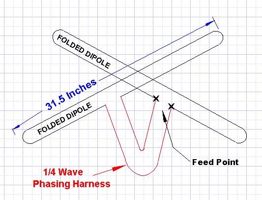
Construction of a gate reflector antenna consists of 2 1/2 wavelength straight dipoles that are oriented 90 degrees from each various other (like a large X). Then feed one dipole 90 degrees out of phase of the 2nd one. One trouble with Turnstile Reflector antennas is that the framework to hold up the reflector part can be difficult.
Luckily (some may disagree) I chose to build my turnstile antenna in my attic. This addresses another problem in that I likewise don't need to concern myself with is weatherizing the antenna.
For the folded dipoles I used 300 ohm television twinlead. What I had on hand was reduced loss "foam" kind. This specific double lead has a rate element of 0.78.
You will certainly additionally observe in the above drawing that the sizes of the dipole aren't what you would certainly expect for 2 meters. This is the length I wound up when I was finished readjusting for minimal SWR. Evidently the rate factor of the twinlead numbers into the resonance of the folded dipole. As they say, "Your mileage might vary" on this length. I would likewise such as to mention that in the illustration over the feedpoint of the folded dipoles is in fact in the center of the folded up dipole. I made the drawing this way for clarity.
The Reflector
In order to get the radiation pattern in the upward instructions for space communications the turnstile antenna needs a reflector beneath it. For a wide pattern the antenna books recommend 3/8 wavelength (30 inches) in between the reflector and the gate. The product I picked for the reflector is normal home window display you can pick up at a hardware shop.
Make sure it is metal screen as there is a non-metal sort of window screen they offer too. I purchased sufficient to outline an 8 foot square on the rafters of my attic. The hardware store could not offer me one huge item for every one of this, so I overlapped items of display by regarding a foot on the joint. From the center of the reflector, I measured up 30 inches (3/8 wavelength). This is where the center, or the going across factor of the folded dipoles lie.
The Phasing Harness
This is not made complex at all. It is absolutely nothing more that a piece of 300 ohm twinlead that is an electric 1/4 wavelength in length. In my situation, with a rate variable of 0.78 the length is 15.75 inches.
The Feedline
I constructed a 4:1 coaxial balun to match the feedline to the antenna In the drawing listed below are the building information.
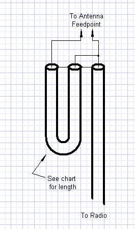
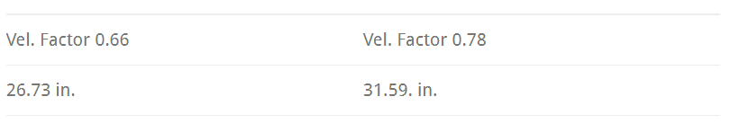
Utilize a high quality, low loss coax if you have a long way to run your feedline. In my case, I only required 15 feet of coax so I used RG-8/ U coax. This is not usually suggested, yet with the feedline this brief there is less than 1 db loss. The measurements for the loophole are dependent on the velocity factor of the coax utilized. Link the coaxial balun to the feedpoint of the turnstile antenna, as shown in the drawing above.
The Outcomes
I am extremely pleased with the efficiency of this antenna. Because I did not require the added expenditure of an AZ/EL rotor, I really felt justified in buying a Mirage preamplifier. Even without the preamplifier, the MIR spacecraft, as well as ISS are full quieting in my receiver when they have to do with 20 deg. or greater in the sky. By including the preamplifier, they are full scale on the S-meter at about 5-10 deg. above the perspective.

CONTACT US


FMUSER INTERNATIONAL GROUP LIMITED.
We are always providing our customers with reliable products and considerate services.
If you would like to keep touch with us directly, please go to contact us
-
![Home]()
Home
-
![Tel]()
Tel
-
![Email]()
Email
-
![Contact]()
Contact


