
VHF Cavity Filters
VHF cavity combiners are critical solutions for modern VHF broadcast networks, enabling stations to merge multiple transmitters into a single, high-performance antenna system.
1. Boost Your Broadcast Power! | Introduction & Overview
At FMUSER, we specialize in RF transmission solutions, designing robust combiner systems that simplify infrastructure while cutting operational costs. This page categorizes our VHF cavity combiners by power capacity (low to high), frequency range, and application compatibility, helping professionals like you quickly identify ideal solutions for:
- Expanding coverage without antenna sprawl
- Scaling power output for dense signal areas
- Modernizing networks to support analog/digital hybrid setups
2. Precision Engineering Meets Reliability | Key Features
FMUSER’s VHF cavity combiners deliver unmatched technical performance and flexibility:
- Ultra-Low Insertion Loss: Maximize signal integrity even at high power (up to 10kW+).
- Military-Grade Durability: All-metal, weatherproof enclosures for 24/7 outdoor operation.
- Industry Compliance: Certified for global safety/EMC standards (CE, FCC, RoHS).
- Frequency Flexibility: Customizable for 87–108 MHz/VHF bands with ±0.5 MHz tuning precision.
- Scalable Design: From compact 2-way combiners for regional stations to 16-port systems for megacity broadcasting.
- Hybrid-Ready: Seamlessly integrates with analog, HD Radio, and DAB+ transmitters.
3. Powering Diverse Broadcast Scenarios | Applications
Here’s how FMUSER’s VHF cavity combiners solve real-world challenges:
- Multi-Transmitter Broadcasting: Combine 4+ transmitters into a single antenna for extended coverage. Low-loss cavity design ensures minimal power waste, even in high-ambient noise zones.
- Redundant Signal Backup: Fail-safe systems for uninterrupted broadcasts during transmitter outages. Automatic RF switching prioritizes active transmitters, eliminating downtime.
- Multi-Channel FM Networks: Transmit multiple channels (e.g., news, music) from one site. Advanced isolation (>50 dB) prevents cross-channel interference.
- Digital Migration Support: Upgrade to digital formats (DAB+/DRM) without replacing existing transmitters. Broadband compatibility integrates analog/digital gear into a unified system.
4. Why FMUSER? Fast. Flexible. Factory-Direct.
- ✅ Cost Efficiency: Factory prices with no middlemen—save 30%+ versus competitors.
- ✅ Always Ready: 95% of combiner models in stock, shipped globally in 3–7 days.
- ✅ Turnkey Solutions: Pre-configure combiners with your specs before delivery.
- ✅ End-to-End Support: 24/7 technical guidance, installation blueprints, and warranty up to 5 years.
- ✅ Custom/OEM: Tailor port counts, power ranges, and finishes to match your site’s needs.
Trusted by broadcasters in 90+ countries, from urban radio hubs to remote TV networks.
5. Smart Buyer’s Guide | Choose the Right Combiner
- Power Handling: Match combiner capacity (e.g., 5kW vs. 20kW) to your transmitter outputs.
- Port Count: Determine how many transmitters need integration (2 to 16+).
- Frequency Plan: Ensure tuning aligns with your VHF band allocations.
- Future-Proofing: Opt for modular designs if expanding later.
Need help? Our engineers offer free system audits to optimize your setup.
-
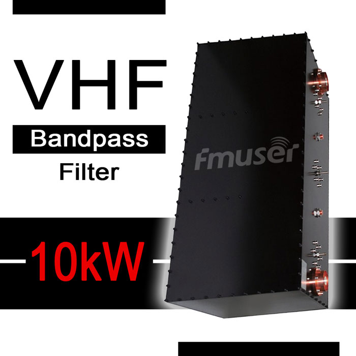
![FMUSER 167-223MHz 10000W VHF Bandpass Filter 10kW VHF Band Pass Filter With Coaxial Cavities for TX RX System]()
Price(USD):Ask for a quotation
Sold:25
-
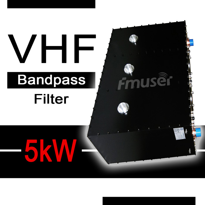
![FMUSER 167-223MHz 5000W VHF Bandpass Filter 5kW VHF Band Pass Filter With Tunable Frequency for TX RX System]()
Price(USD):Ask for a quotation
Sold:17
-
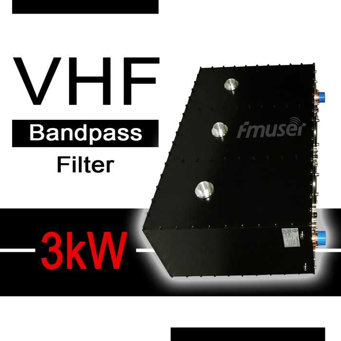
![FMUSER 167-223MHz 3000W VHF Bandpass Filter 3kW VHF Band Pass Filter With Tunable Frequency for TX RX System]()
Price(USD):Ask for a quotation
Sold:29
-
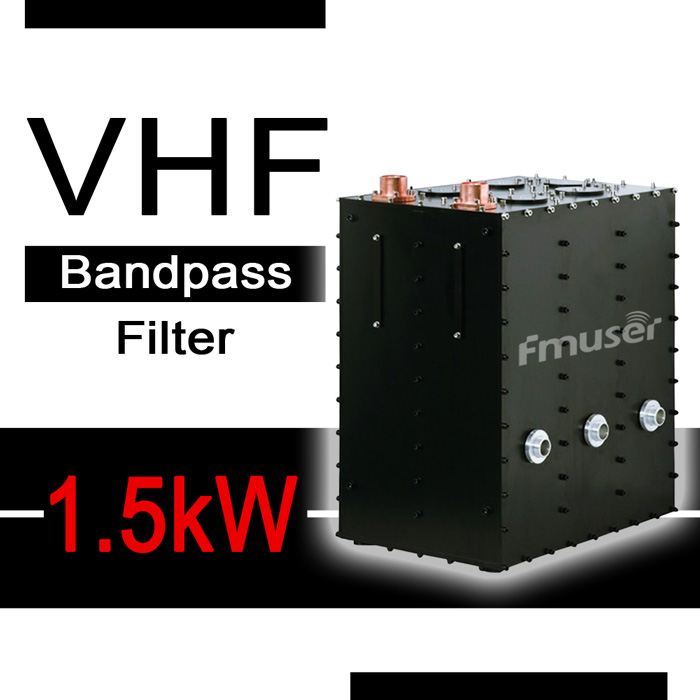
![FMUSER 167-223MHz 1500W VHF Bandpass Filter 1500W VHF Band Pass Filter With Tunable Frequency for TX RX System]()
Price(USD):Ask for a quotation
Sold:30
-
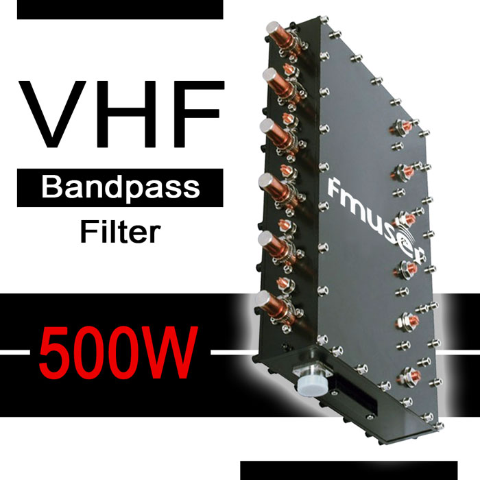
![FMUSER 167-223MHz 500W VHF Bandpass Filter 500W VHF Band Pass Filter With Coaxial Cavities for TX RX System]()
Price(USD):Ask for a quotation
Sold:24
-
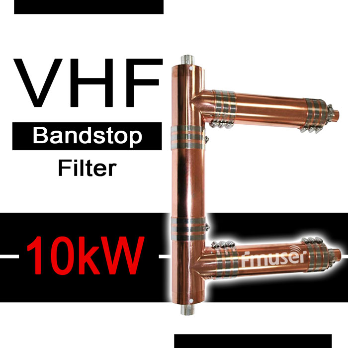
![FMUSER 10kW VHF Bandstop Filter 167-223 MHz 10000W Band Stop Filter High Power VHF Band Reject Filter VHF Notch Filter for TX RX System]()
Price(USD):Ask for a quotation
Sold:11
-
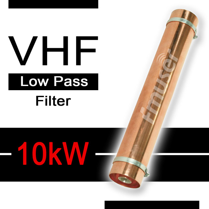
![10kW VHF Low Pass Filter 167-223 MHz Coaxial Lowpass Filter with Different Frequency and Power Level for TX RX System]()
Price(USD):Ask for a quotation
Sold:34
- How to correctly use VHF cavity filter in broadcast station?
- 1. Select the appropriate filter based on the desired frequency range and power requirements.
2. Make sure the filter is properly installed in the transmitter line, keeping the filter as close to the transmitter as possible.
3. Test the filter for proper insertion loss and frequency response.
4. Monitor the filter for any sign of deterioration or damage.
5. Make sure the power rating of the filter is not exceeded.
6. Replace the filter if it is not performing as expected.
7. Avoid using the filter for frequencies outside its specified range.
8. Avoid using the filter in an environment with excessive dust or humidity.
9. Avoid using the filter in an environment with extreme temperatures.
- How does VHF cavity filter work in VHF broadcast station?
- A VHF cavity filter works by trapping unwanted frequencies between two or more tuned resonant cavities. The cavities are coupled together to form a filter with a specific bandwidth. As the frequency passes through the filter, the unwanted signal is attenuated, allowing only the desired signal to pass. The amount of attenuation is determined by the quality factor (Q) of the cavities, which can be adjusted by changing the size of the inner cavities. The filter will reject any signals outside of the desired frequency range, allowing the desired signal to pass through with minimal interference.
- How to choose the best VHF cavity filter?
- When choosing a VHF cavity filter for a broadcast station, it is important to consider several factors, including the desired frequency range, power requirements, and budget. It is also important to ensure that the filter is properly installed and tested for proper insertion loss and frequency response. Additionally, it is important to monitor the filter for any signs of deterioration or damage. Finally, it is important to make sure that the power rating of the filter is not exceeded and that the filter is suitable for the environment in which it will be used.
- Why VHF cavity filter is important and is it necessary for a VHF broadcast station?
- VHF cavity filters are important for a VHF broadcast station because they protect the broadcasting signal from interference. This is necessary to ensure that the desired signal is clear and that any unwanted frequencies are blocked. By filtering out these unwanted frequencies, the signal is protected from distortion and interference, providing a better listening experience. Additionally, using a VHF cavity filter can reduce the power necessary to broadcast, saving money and reducing the amount of energy used.
- How many types of VHF cavity filter are there?
- There are several types of VHF cavity filters, including bandpass filters, notch filters, lowpass filters, and highpass filters. Bandpass filters allow for a specific frequency range to pass through, while notch filters reject a specific frequency. Lowpass filters allow for all frequencies below a certain point to pass, while highpass filters allow for all frequencies above a certain point to pass. Each type of filter offers different levels of attenuation and can be used in different situations depending on the desired frequency range and power requirements.
- How to correctly connect a VHF cavity filter in a VHF broadcast station?
- To properly connect a VHF cavity filter in a VHF broadcast station, the filter should be installed as close to the transmitter as possible. The filter should be connected in the transmitter line between the transmitter and antenna. The filter should be tested for proper insertion loss and frequency response before it is used. Additionally, the power rating of the filter should not be exceeded and the filter should be monitored for any signs of deterioration or damage.
- What are the equipment related to VHF cavity filter in a broadcast station?
- The equipment related to a VHF cavity filter in a broadcast station includes the filter itself, a transmitter, and an antenna. The filter should be installed in the transmitter line between the transmitter and antenna. Additionally, a power meter and frequency analyzer may be necessary for testing the filter for proper insertion loss and frequency response.
- What are the most important specifications of VHF cavity filter?
- The most important physical and RF specifications of a VHF cavity filter are the frequency range, insertion loss, power rating, and Q factor. The frequency range determines which frequencies can pass through the filter, while the insertion loss is the amount of signal attenuation the filter provides. The power rating determines how much power the filter can handle without damage, and the Q factor determines the amount of attenuation at a given frequency.
- As an engineer, how to maintain a VHF cavity filter in a VHF broadcast station?
- As an engineer, it is important to properly maintain a VHF cavity filter in a VHF broadcast station. This includes monitoring the filter for any signs of deterioration or damage, as well as testing the filter for proper insertion loss and frequency response. Additionally, it is important to make sure the power rating of the filter is not exceeded and that the filter is suitable for the environment in which it will be used. If any problems are detected, the filter should be replaced as soon as possible.
- How to repair a VHF cavity filter if it fails working in a VHF broadcast station?
- If a VHF cavity filter fails working in a VHF broadcast station, it should be inspected to determine the cause of the failure. Depending on the cause, the filter may need to be repaired or replaced. If the filter can be repaired, the broken parts should be removed and replaced with new parts that meet the original specifications. If the filter cannot be repaired, a new filter should be purchased and installed in the transmitter line.
- How to choose the right packaging for VHF cavity filter during transportation?
- When choosing the right packaging for a VHF cavity filter for a VHF broadcast station, it is important to consider the size and weight of the filter, as well as the environment in which it will be stored and transported. The packaging should be strong enough to protect the filter from damage, and it should be designed to keep the filter dry and free from dust and debris. Additionally, the filter should be secured in the packaging to prevent movement during transport, and the package should be labeled correctly to ensure that it is handled correctly.
- What kind of material is the casing of the VHF cavity filter generally made of?
- The casing of a VHF cavity filter is generally made of metal, such as aluminum or steel. These materials are chosen for their strength, durability, and ability to block electromagnetic interference. The material of the casing will not affect the performance of the filter, as long as it is properly sealed.
- What is the basic structure of VHF cavity filter?
- The basic structure of a VHF cavity filter consists of two or more tuned resonant cavities that are coupled together. The cavities are designed to trap unwanted frequencies, allowing the desired signal to pass through. The size of the inner cavities determines the quality factor (Q) of the filter, which determines the amount of attenuation at a given frequency. The Q factor is the most important factor in determining the performance of the filter, and the filter will not work as expected if any of the cavities are missing or not properly tuned.
- In a broadcast station, who should be assigned to manage VHF cavity filter?
- In a broadcast station, the VHF cavity filter should be managed by a qualified engineer who is familiar with the filter and its maintenance requirements. This person should possess good communication skills, as well as technical knowledge and experience in the operation and maintenance of VHF cavity filters. Additionally, they should have the ability to recognize any signs of deterioration or damage, and be able to troubleshoot and repair the filter if necessary.
- How are you?
- I am fine
CONTACT US


FMUSER INTERNATIONAL GROUP LIMITED.
We are always providing our customers with reliable products and considerate services.
If you would like to keep touch with us directly, please go to contact us
-
![Home]()
Home
-
![Tel]()
Tel
-
![Email]()
Email
-
![Contact]()
Contact


