
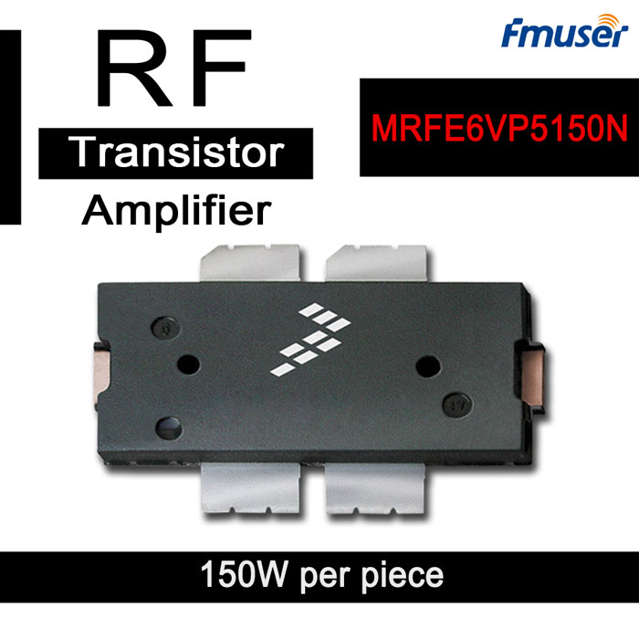
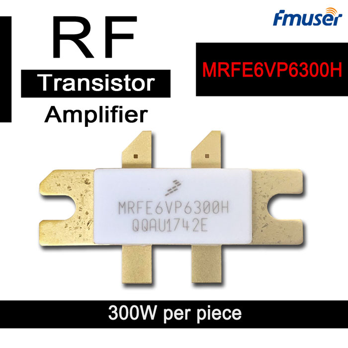
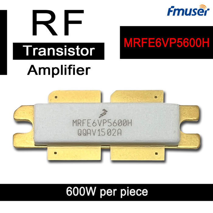
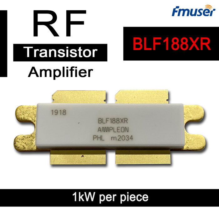
High Power RF Transistors
RF Power MOSFET Transistors are pivotal components in broadcasting, telecom, and industrial systems, delivering unmatched power efficiency and signal control.
1. Seamless Solutions for Modern Demands
At FMUSER, a leader in RF and microwave solutions, we simplify your selection process by categorizing our transistors based on output power, operational frequency (1MHz–6GHz), and application-specific designs, ensuring professionals quickly pinpoint the ideal fit for 5G base stations, medical equipment, or high-power amplifiers.
2. Unmatched Innovation at Your Fingertips
- Robust Durability: Built for 24/7 operation in extreme temperatures (-40°C to +150°C).
- Certified Performance: ISO 9001-certified manufacturing with RoHS compliance.
- Cutting-Edge Tech: Silicon Carbide (SiC)/GaN hybrid designs for ultra-low switching losses.
- Scalability: Solutions ranging from 200W entry-level modules to 5000W industrial-grade systems, tailored for hobbyists, integrators, and OEMs.
3. Powering Industries Globally
High power RF transistors are used in a variety of applications. One of the most common uses is in broadcast transmitters, where they are used to amplify the radio signal before it is broadcast.
- Telecom Infrastructure: Enable high-efficiency RF amplification in 5G base stations, reducing energy costs by 30% compared to legacy modules.
- Medical Diathermy Systems: Ensure stable, high-frequency output for non-invasive treatments with FMUSER’s EMI-shielded transistors.
- Broadcast Transmitters: Achieve ultra-low distortion for crisper signal transmission in FM/AM radio stations.
- Plasma Generators: Optimize ionization efficiency in industrial plasma systems using our high-power, fast-switching designs.
4. Why FMUSER Leads the Market
- Cost & Speed: Enjoy factory-direct pricing, same-day shipping, and 90% in-stock availability.
- Turnkey Solutions: Pre-configured transistor kits with matching heat sinks and drivers.
- Customization: Tailored packages for aerospace, defense, or IoT applications, backed by on-site installation support.
- Proven Success: Trusted by Ericsson, Siemens, and over 1,200 SMEs globally.
5. Your Path to Optimal Performance
- Power Needs: Match transistor wattage (e.g., 500W for small radio stations vs. 3kW for industrial).
- Frequency Range: Select models optimized for LF/HF (1–30MHz) or VHF/UHF (100MHz–3GHz).
- Budget: Balance upfront costs with FMUSER’s 5-year warranty for long-term ROI.
- What is a RF transistor and how it works?
- A RF transistor, or radio frequency transistor, is a type of transistor designed to work in the high frequency range of radio waves, typically from 10 MHz to several GHz. These transistors are made from semiconductor materials, such as silicon or gallium arsenide, and are used in a variety of electronic applications that require a high-frequency signal amplification and switching.
The operation of a RF transistor is similar to that of any other transistor. When a voltage is applied to the base terminal, a current flows through the base-emitter junction, which in turn controls the flow of current through the collector-emitter junction. The collector-emitter current is proportional to the base-emitter current, which is controlled by the base-emitter voltage. In a RF transistor, the collector-emitter current is typically in the range of a few milliamperes to several amperes, while the base-emitter current is typically in the range of microamperes. This high gain and low input current makes RF transistors ideal for high-frequency applications.
RF transistors are used in a wide range of applications, including radio and television broadcasting, mobile phones, radar systems, satellite communications, and medical equipment. They are commonly used as high-frequency amplifiers, oscillators, and switches. RF transistors are also used in low noise amplifier circuits, where sensitivity and noise figure are important. In addition, RF transistors are used in power amplifier circuits, where high gain and high output power are required. Overall, RF transistors are essential components in modern electronics, especially in wireless communication systems.
- What is a RF mosfet transistor and how it works?
- A RF MOSFET transistor, also known as a metal oxide semiconductor field effect transistor, is a type of transistor that is designed to operate at high radio frequencies. RF MOSFET transistors are widely used in RF and microwave circuits due to their high efficiency and low noise. They are commonly used in applications such as wireless communications, high-frequency amplifiers, and radar.
The RF MOSFET transistor is a three-terminal device with a source, gate, and drain. The source and drain terminals are connected to the two ends of the semiconductor channel, which is a thin layer of conducting material that is formed on top of an insulating substrate. The gate terminal is separated from the semiconductor channel by a thin insulating layer. When a voltage is applied to the gate terminal, it forms an electric field, which controls the flow of current between the source and drain terminals.
The RF MOSFET transistor works by using a voltage to control the flow of current through the semiconductor channel. When a voltage is applied to the gate of the transistor, it creates an electric field that either allows or blocks the flow of current between the source and drain. This control of the current enables the transistor to amplify or switch signals at high frequencies.
RF MOSFET transistors are commonly used in high-frequency circuits because of their high switching speed and low noise. They are also known for their high power handling capabilities and low junction capacitance. They are used in a range of applications, including wireless communication systems, power amplifiers, and microwave ovens.
In summary, RF MOSFET transistors are a type of transistor that is designed to operate at high radio frequencies. They operate based on the flow of current being controlled by a voltage applied to the gate terminal. They are widely used in RF and microwave circuits, and their key features include high efficiency, low noise, and high power handling capabilities.
- How to differ RF transistor, RF power transistor, high power RF transistor, RF mosfet transistor?
- Yes, there are differences between these types of transistors.
RF transistor is a general term used to refer to any transistor that is designed to operate at radio frequencies, typically in the range of a few MHz up several GHz. RF transistors can be either bipolar or field-effect transistors (FETs) and can be used in low or high power applications.
RF power transistor is a type of RF transistor that is designed to handle high output power levels, typically in the range of watts to kilowatts, with a relatively low gain. These transistors are typically used in applications such as broadcast transmitters, radar systems, and industrial heating systems.
High power RF transistor is a subset of RF power transistors that are optimized to handle even higher output power levels. These transistors are designed with larger semiconductor dies, thicker interconnects, and specialized packaging to effectively dissipate the higher levels of electrical energy. High power RF transistors typically have a lower gain than regular RF transistors since high gain can cause instability and self-oscillation at high output power levels.
RF MOSFET transistor, or metal-oxide-semiconductor field-effect transistor, is a type of transistor where the current flow is controlled by an electric field applied to a gate terminal. RF MOSFET transistors are typically used in high-frequency applications and are known for their high input impedance and low noise.
In summary, while all of these transistors are designed to operate at radio frequencies, they have differences in terms of power handling capability, packaging, gain, and other performance characteristics.
- How to test a high power RF transistor?
- Testing a high power RF transistor requires specialized equipment, including an RF power meter, network analyzer, and a load pull setup. Here are the basic steps to follow when testing a high power RF transistor:
1. Identify the pinout: The first step is to identify the pinout of the transistor and ensure it is properly connected to the test fixtures. Consult the datasheet or reference manual for the specific transistor to identify the correct pinout.
2. Bias the transistor: Apply a DC bias voltage to the transistor via the bias tee or bias circuit. This is important to ensure the transistor is operating in its linear region.
3. Connect the transistor to a network analyzer: Use RF probes or appropriate RF fixtures to connect the transistor to a network analyzer. Ensure the connections are tight and secure.
4. Measure the S-parameters: Use the network analyzer to measure the S-parameters of the transistor. This will provide information on the transistor's impedance and gain characteristics.
5. Evaluate power output: Connect the transistor to an RF power meter, and measure the power output as you vary the input power. This will help determine the transistor's linear and non-linear characteristics.
6. Load pull setup: Use a load pull setup to evaluate the transistor's performance at different output loads. This involves varying the impedance at the transistor's output, which affects the amount of power the transistor can deliver.
7. Repeat the test for different frequency ranges: Repeat the tests for different frequency ranges to fully evaluate the transistor's performance.
These steps provide a basic overview of how to test a high power RF transistor. However, the process can vary depending on the specific transistor and testing equipment being used. It's important to consult the manufacturer's datasheet and user manual for the specific test procedures and recommendations. Also, it's important to use appropriate safety precautions when working with high power RF transistors, as they can generate potentially harmful levels of radiation.
- How to implement a discrete rf transistor?
- Implementing a discrete RF transistor involves several steps, including selecting the appropriate transistor, determining the necessary biasing and matching circuitry, and designing the layout for the circuit. Here are some basic steps to follow when implementing a discrete RF transistor:
1. Choose the Transistor: The first step is to choose an appropriate transistor for your application. Factors to consider include the frequency range, power requirements, gain, and noise characteristics. Depending on the application, you can choose between bipolar junction transistors (BJTs) or field-effect transistors (FETs).
2. Biasing Circuitry: Once you have selected the transistor, the next step is to determine the appropriate biasing circuitry. While the specifics of the biasing circuit will depend on the particular transistor and application, typically, a transistor requires either a DC voltage (for a BJT) or a DC current (for an FET) applied to it. This is important to ensure that the transistor is operating in its linear region.
3. Matching Circuitry: Matching circuitry is critical to ensure that the transistor can transfer the maximum amount of power to the load. Matching circuitry is used to transform the input and output impedance of the transistor to match the impedances in the rest of the circuit. For high-frequency circuits, lumped-element matching networks consisting of inductors, capacitors, and transformers are often used.
4. Layout Design: The next step in implementing a discrete RF transistor is to design the layout. This involves creating the physical circuit board layout that matches the schematic. It is important to use best practices for high-frequency layout design and avoid creating loops and gaps in the ground plane. The transistor should be placed as close as possible to the matching circuitry, and the layout should be designed to minimize parasitic capacitance and inductance.
5. Testing: Once the circuit is assembled, it should be tested to ensure that it is operating correctly. Use test equipment such as a signal generator, oscilloscope, and spectrum analyzer to test the circuit's frequency response, gain, and power output. This will allow you to identify and correct any issues that may arise.
In summary, implementing a discrete RF transistor involves selecting an appropriate transistor, designing a biasing and matching circuitry, designing a high-frequency layout, and testing the circuit. This process requires a good understanding of the transistor's characteristics and the principles of high-frequency circuit design.
- What are the structures of a High power RF transistor?
- A high power RF transistor generally has a similar structure to a standard RF transistor, with some modifications to handle the higher power levels. Here are some possible structures of a high power RF transistor:
1. Bipolar Junction Transistor (BJT): A high power BJT typically consists of a heavily doped substrate with two layers of opposite doping sandwiched in between. The collector region is usually the largest area of the device, and it is made as wide as possible to handle more power. The emitter is usually a highly doped region, while the base is a lightly doped region. High power BJTs often have multiple emitter fingers to distribute the current across the emitter region.
2. Metal Oxide Semiconductor Field Effect Transistor (MOSFET): A high power MOSFET usually consists of a semiconductor substrate with an insulating layer on top, followed by a conducting gate electrode. The source and drain regions are doped areas that are patterned on either side of the gate electrode. High power MOSFETs often use a double-diffused MOSFET (DMOS) structure, which involves introducing a heavily doped P layer between the N+ source and drain regions, to handle more power.
3. Gallium Nitride (GaN) Transistor: GaN transistors have become increasingly popular for high power RF applications. A high power GaN transistor typically has a thin GaN layer grown on top of a silicon carbide (SiC) substrate, with a metal gate electrode on top. The source and drain regions are doped areas patterned on either side of the gate electrode, and they can be either Schottky or ohmic contacts.
In summary, high power RF transistors have similar structures to standard RF transistors, but with modifications to handle higher power levels. The structure depends on the type of transistor and the materials used. Bipolar junction transistors (BJTs), metal oxide semiconductor field effect transistors (MOSFETs), and gallium nitride (GaN) transistors are commonly used for high power RF applications, and they all have some differences in their structures and performance characteristics.
- What are the appliactions of a High power RF transistor?
- Sure, here are some applications of high power RF transistors:
1. Broadcast Stations: High power RF transistors are commonly used in broadcast stations for transmitting radio and television signals over long distances. They can be used for both FM and AM broadcast signals.
2. Radar Systems: High power RF transistors are also used in radar systems for detecting objects in the air, such as airplanes, missiles, or weather patterns. They are typically used in the UHF and VHF frequency ranges.
3. Medical Applications: High power RF transistors are sometimes used in medical applications, such as in MRI machines. They can help to generate the magnetic fields required for imaging.
4. Industrial Applications: High power RF transistors can also be used in various industrial applications, such as in welding machines, plasma cutting machines, and RF heating equipment.
5. Jamming Devices: High power RF transistors can be used in jamming devices, which are used to disrupt radio signals in a certain frequency range. These devices can be used by military or law enforcement agencies as a means of blocking enemy communication signals.
6. Ham Radio: High power RF transistors are also used in amateur radio (ham radio) applications, particularly in amplifiers that boost the input signal to higher power levels for transmission.
Overall, the primary applications of high power RF transistors are in the transmission and amplification of radio frequency signals in various industries and applications.
- What are common high power RF transistor for broadcast transmitters?
- There are several high power RF transistors available for use in FM broadcast transmitters. Here are some examples:
1. NXP BLF188XR: The NXP BLF188XR is a high power LDMOS transistor designed for use in FM broadcast transmitters. It offers up to 1400 watts output power and is commonly used in transmitters with output power levels of 5 kW or more. This transistor was first introduced in 2012 by NXP Semiconductors.
2. STMicroelectronics STAC2942: The STAC2942 is a high power MOSFET transistor designed for use in FM broadcast transmitters. It offers up to 3500 watts output power and is commonly used in transmitters with output power levels of 10 kW or more. STMicroelectronics introduced this transistor in 2015.
3. Toshiba 2SC2879: The Toshiba 2SC2879 is a high power bipolar transistor designed for use in FM broadcast transmitters. It offers up to 200 watts output power and is commonly used in transmitters with output power levels of 1 kW or less. This transistor was first manufactured by Toshiba in the 1990s and is still in use today.
4. Mitsubishi RD100HHF1: The Mitsubishi RD100HHF1 is a high power MOSFET transistor designed for use in FM broadcast transmitters. It offers up to 100 watts output power and is commonly used in transmitters with output power levels of 500 watts or less. This transistor was first introduced in the early 2000s by Mitsubishi Electric Corporation.
5. Freescale MRFE6VP61K25H: The Freescale MRFE6VP61K25H is a high power LDMOS transistor designed for use in FM broadcast transmitters. It offers up to 1250 watts output power and is commonly used in transmitters with output power levels of 5 kW or more. This transistor was first introduced in 2011 by Freescale Semiconductor (now part of NXP Semiconductors).
In terms of who first manufactured these high power RF transistors, each of these companies developed their own respective transistors independently. NXP Semiconductors and Freescale Semiconductor (now part of NXP Semiconductors) are both major players in the RF power transistor market, while Toshiba and Mitsubishi have also been producing high power RF transistors for many years.
Overall, the choice of transistor will depend on a number of factors, including the transmitter's output power level, operating frequency, gain requirements, and other performance specifications. The availability of these transistors can vary depending on location and market demand.
- How many types of High power RF transistor are there?
- There are several types of high power RF transistor, each with its own unique characteristics. Here are some of the main types, along with their characteristics:
1. Bipolar Transistors: Bipolar transistors are a type of transistor that use both electrons and holes as charge carriers. They are generally high-power devices with high voltage and current capabilities. They are commonly used in broadcast applications such as FM and AM broadcasting. Bipolar transistors are typically less efficient than other types of high power RF transistors, and can generate significant heat.
2. MOSFET Transistors: MOSFET transistors are another type of high power RF transistor that are commonly used in broadcasting applications. They offer good efficiency and low noise, making them suitable for use in transmitters for FM broadcasting, although they are also used in other types of broadcasting systems. MOSFET transistors can operate at high frequencies and generate less heat than bipolar transistors.
3. LDMOS Transistors: LDMOS stands for "Laterally Diffused Metal Oxide Semiconductor". LDMOS transistors are widely used in modern FM broadcast transmitters due to their high efficiency, low thermal resistance, and excellent linearity. LDMOS transistors offer a good balance of power, efficiency, and reliability and are suitable for high power applications.
4. GaN Transistors: GaN stands for "Gallium Nitride". GaN transistors offer high power and efficiency while also being capable of operating at high frequencies. They are suitable for use in broadcast applications such as FM broadcasting and are known for their low noise.
In terms of manufacturers, some of the biggest players in the high power RF transistor market include NXP Semiconductors, STMicroelectronics, Toshiba, and Mitsubishi Electric Corporation. These companies produce a wide range of high power RF transistors, each with its own unique characteristics and advantages.
The differences between the different types of high power RF transistors can be significant in terms of their performance characteristics, including their frequency range, broadcasting coverage, power output, efficiency, and cost. For example, LDMOS and GaN transistors are often more efficient and generate less heat than bipolar transistors, but they may be more expensive.
In terms of installation, repair, and maintenance, high power RF transistors require specialized knowledge and equipment, and should always be handled by experienced technicians. Proper installation and maintenance are critical for ensuring that the amplifier remains stable, efficient, and reliable. Regular maintenance and troubleshooting can also help prevent costly downtime and repair costs.
Overall, the choice of high power RF transistor will depend on a number of factors, including the specific application, performance requirements, and budget considerations. It's important to select a transistor that is well-suited to the application and to work with a reputable supplier who can provide guidance and support throughout the selection and installation process.
- What are common terminologies of high power RF transistor?
- Here are some common terminologies related to high power RF transistors, along with an explanation of what they mean:
1. Collector-Emitter Voltage (Vce): Vce refers to the maximum voltage that can be applied across the collector and emitter terminals of a high power RF transistor. Exceeding this voltage can cause the transistor to fail.
2. Collector Current (Ic): Ic refers to the maximum current that can be conducted through the collector terminal of a high power RF transistor. Exceeding this current can cause the transistor to fail.
3. Maximum Power Dissipation (Pd): Pd refers to the maximum amount of power that a high power RF transistor can dissipate as heat without exceeding its operating temperature. Exceeding this value can cause the transistor to overheat and fail.
4. Operating Frequency (f): The operating frequency refers to the frequency range within which a high power RF transistor can operate at its specified performance levels.
5. Transistor Gain (hFE or Beta): Transistor gain refers to the amplification factor of a high power RF transistor, or the ratio of the output current to the input current.
6. Output Power (Pout): Output power refers to the maximum power that can be delivered by a high power RF transistor to the load (such as an antenna) without exceeding its specified maximum ratings.
7. Efficiency: Efficiency refers to the ratio of output power to input power in a high power RF transistor. High efficiency transistors are desirable in RF amplifiers because they waste less power as heat and generate less unwanted noise.
8. Impedance Matching: Impedance matching refers to the process of ensuring that the input and output impedance of the transistor circuit is matched to the impedance of the load (usually an antenna). Proper impedance matching helps to maximize the power transfer between the transistor and the load.
9. Thermal Resistance (Rth): Thermal resistance refers to the ability of a high power RF transistor to dissipate heat. Lower thermal resistance values indicate better heat dissipation and higher cooling capacity, which is important to prevent the device from overheating.
10. Resonant Frequency (f0): Resonant frequency refers to the frequency at which a high power RF transistor's circuit resonates and has the highest gain. Matching the transistor's resonant frequency to the frequency of the signal being amplified helps to maximize its performance.
Understanding these terminologies is important for selecting the right high power RF transistor for a specific application, as well as for ensuring proper installation, operation, and maintenance.
- What are the most important specifications of a High power RF transistor?
- The most important physical and RF specifications of a high power RF transistor include:
1. Power Output: This is the maximum power that the transistor can deliver to the load without exceeding its maximum ratings.
2. Operating Frequency Range: This refers to the range of frequencies at which the transistor can operate at its specified performance level.
3. Collector-Emitter Voltage: This is the maximum voltage that can be applied across the collector and emitter terminals of the transistor without causing it to fail.
4. Maximum Current: This is the maximum current that the transistor can conduct through the collector terminal without causing it to fail.
5. Efficiency: This is the ratio of output power to input power and indicates how much of the input power the transistor is able to convert into useful output power.
6. Gain: This is the amplification factor of the transistor and indicates how much the input signal is amplified by the transistor.
7. Thermal resistance: This is the ability of the transistor to dissipate heat without exceeding its maximum operating temperature. Lower thermal resistance values indicate better heat dissipation and higher cooling capacity.
8. Mounting Type: High power RF transistors can be mounted using various methods, such as via through-hole or surface-mount technology.
9. Package Type: This refers to the physical package or housing of the transistor, which can vary in size, shape, and material.
10. RF Matching: This refers to the process of matching the input and output impedance of the transistor to that of the load, which helps to maximize power transfer and reduce noise.
Understanding these physical and RF specifications is critical for selecting the right high power RF transistor for a specific application. It's important to consider the nature of the application, such as the required output power, operating frequency, and efficiency, when selecting a transistor. Proper thermal management and impedance matching are also important for ensuring proper operation and avoiding damage to the transistor.
- Do high power RF transistors vary in different applications?
- High power RF transistors used in different broadcast transmitters (e.g., UHF, VHF, TV, AM, FM, etc.) have varying characteristics and are used differently based on the specific requirements of the transmitter. Here are the differences between high power RF transistors used in various broadcast transmitters:
UHF Transmitters:
1. Advantages: High efficiency, power output and operating frequency.
2. Disadvantages: High cost and the need for special care and cooling due to high power consumption.
3. Applications: Typically used in TV broadcasting and other applications requiring high frequency and high power output.
4. Performance: High stability and good linearity.
Structures: Typically use MOSFET or LDMOS technology.
5. Frequency: UHF frequency range (300MHz - 3GHz).
6. Installation and Maintenance: High precision installation and maintenance required due to their high output power.
VHF Transmitters:
1. Advantages: High output power, efficiency, and reliability.
2. Disadvantages: Can be costly due to the complexity of the technology.
3. Applications: Ideal for use in FM radio and other VHF broadcasting applications.
4. Performance: High-linearity, stable output power.
5. Structures: Most commonly use bipolar technology (BJT), though MOSFETs can also be used.
6. Frequency: VHF frequency range (30 - 300MHz).
7. Installation and Maintenance: Requires regular maintenance to ensure the stability of output power.
TV Transmitters:
1. Advantages: High output power, bandwidth, and efficiency.
Disadvantages: High initial cost, and complex design.
2. Applications: Ideal for TV broadcasting, Mobile TV, and other video/audio transmission applications.
3. Performance: Excellent linearity and stability.
4. Structures: Use multiple RF driver stages followed by the final high power amplifier stage typically using LDMOS technology.
5. Frequency: Various frequency bands are used, depending on the transmission standard (DTV, analog, etc.) usually in the UHF or VHF bands.
6. Installation and Maintenance: High precision installation and maintenance required due to high output power and complex circuit design.
AM Transmitters:
1. Advantages: Low complexity, low cost, wide application range.
2. Disadvantages: Relatively low power compared to other broadcast transmitters.
3. Applications: Ideal for AM radio and other low-power communication applications.
4. Performance: Good bandwidth, but lower output power than other broadcast transmitters.
5. Structures: Typically use high-power bipolar transistors (BJT) or FETs.
6. Frequency: AM frequency range (530kHz - 1.6MHz).
7. Installation and Maintenance: Simple installation, with low maintenance requirements.
FM Transmitters:
1. Advantages: High bandwidth, transmission efficiency and stability.
2. Disadvantages: Can be costly.
3. Applications: Ideal for FM radio and other high-quality audio transmission applications.
4. Performance: High power output and stable frequency.
5. Structures: Typically use high power LDMOS transistors.
6. Frequency: FM frequency range (88 -108MHz).
7. Installation and Maintenance: Precise installation and regular maintenance needed for optimal performance.
Overall, high-power RF transistors used in different broadcasting transmitters have varying characteristics that are suited to different applications. The choice of high-power RF transistor depends on factors such as the required frequency range, power output, efficiency, bandwidth, and cost, among others. It is important to note that proper installation, maintenance and repairment is crucial for all transmitters using high-power RF transistors in order to ensure optimal performance, reliability and longevity of the components.
- How to choose the best high power RF transistor for broadcasting?
- Choosing the best high-power RF transistor for a broadcasting station depends on several factors such as frequency range, power output, efficiency, and cost. Here is a list of specifications and classifications to consider when selecting a high-power RF transistor for various broadcasting stations:
1. UHF Broadcasting Station: For UHF broadcasting stations, the best high-power RF transistor would be one that operates in the UHF frequency range (300 MHz to 3 GHz), has a high power output, and high efficiency. Typically, a laterally-diffused MOSFET (LDMOS) transistor is used for UHF stations due to its high power output, linearity, and efficiency.
2. VHF Broadcasting Station: For VHF broadcasting stations, the best high-power RF transistor would be one that operates in the VHF frequency range (30 MHz to 300 MHz) and has a high output power and efficiency. Bipolar junction transistor (BJT) technology is typically used for VHF stations due to its high output power and efficiency.
3. FM Radio Station: For FM radio stations, the best high-power RF transistor would be one that operates in the FM frequency range (88 MHz to 108 MHz) and has a high linearity and efficiency. LDMOS technology is commonly used for FM stations due to its high linearity and efficiency.
4. TV Broadcasting Station: For TV broadcasting stations, the best high-power RF transistor would be one that operates in the frequency band used by the TV transmission standard and has a high output power and efficiency. LDMOS technology is commonly used in TV broadcasting transmitters due to its high linearity and efficiency.
5. AM Broadcasting Station: For AM broadcasting stations, the best high-power RF transistor would be one that operates in the AM frequency range (530 kHz to 1.6 MHz) and has a high power output and efficiency. BJT or FET technology can be used for AM stations due to their high efficiency.
It is important to consider other factors such as cost, availability, and vendor support when selecting the appropriate high-power RF transistor for each broadcasting station. It is also recommended to consult with a qualified RF engineer or consultant to ensure the optimal selection of the high-power RF transistor for the specific broadcasting station.
- How a high power RF transistor is made and installed?
- The full process of a high-power RF transistor from production to installation in a broadcasting station involves several stages, including fabrication, testing, packaging, and distribution. Here is a detailed explanation of each of these stages:
1. Fabrication: The first stage of producing a high-power RF transistor involves fabricating the transistor using various semiconductor layering processes. The fabrication process involves a combination of clean-room procedures, lithography, etching, deposition, and other processes that build up the transistors' structure.
2. Testing: Once the high-power RF transistor is fabricated, it is tested for electrical characteristics such as gain, power output, and linearity. Testing is performed using specialized test equipment, including network analyzers, spectrum analyzers, and oscilloscopes.
3. Packaging: After the high-power RF transistor is tested, it is packaged into an appropriate housing. The package protects the transistor from damage during handling and installation and provides a suitable platform for connections to the rest of the circuit. Packaging also includes wire bonding, attaching leads, and adding heat sinks to improve the thermal behaviour of the transistor.
4. Distribution: High-power RF transistors can be distributed directly to the manufacturer's sales channels, or through a network of official distributors. Transistors may be sold as individual units or in batches, depending on the manufacturer's preferences.
5. Installation: Once the high-power RF transistor is purchased and received by the broadcasting station, it is integrated into the transmitter's circuitry. The transistor is installed using the appropriate mounting techniques, including thermal interface materials, such as thermal grease, pads, or phase-change materials. The installation process follows strict installation manuals or procedures to ensure that the transistor is installed correctly, minimizing the risk of damage to the transistor.
6. Testing and Maintenance: After installation, the high-power RF transistor is tested again to ensure that it is functioning properly. The broadcasting station will continue to monitor the transistor for proper operation, as RF transistors can degrade over time and lose their performance characteristics, leading to reduced output power and possible failure. Routine maintenance is carried out on the transmitter and its components to ensure long-term performance and reliability.
Overall, the full process of a high-power RF transistor from production to final installation in a broadcasting station involves a combination of specialized fabricating, testing, packaging, and distribution processes. Once installed, maintenance, and careful monitoring are required to ensure reliable and long-term operation of the high-power RF transistor.
- How to maintain a high power RF transistor correctly?
- Proper maintenance of high-power RF transistors in a broadcast station is crucial to ensure reliable and long-term operation. Here are some steps to follow to correctly maintain a high-power RF transistor in a broadcast station:
1. Follow manufacturer's guidelines: Always follow the manufacturer's recommended maintenance procedures and schedule. The maintenance schedule may vary depending on the manufacturer, the type of high-power RF transistor, and the environmental conditions of the broadcast station.
2. Monitor the operating conditions: Regularly monitor the operating conditions of the high-power RF transistor, such as temperature, voltage, and current levels. Ensure that the operating conditions remain within the recommended ranges to prevent damage to the transistor.
3. Keep the transistor clean: Dust and debris can build up on the surface of the high-power RF transistor, which can negatively affect its performance and life. Maintain the cleanliness of the transistor by cleaning it periodically with a soft cloth and a non-abrasive cleaning solution.
4. Ensure proper thermal management: High-power RF transistors generate a significant amount of heat during operation, which can negatively impact their performance. Proper thermal management, such as using heat sinks and cooling fans, helps to dissipate the heat and ensure that the transistor operates within their temperature limits.
5. Regular testing and tuning: High-power RF transistors require regular testing to ensure that they are functioning correctly. Periodic testing can identify potential problems before they become severe. Tuning the circuitry of the transmitter concerning the transistor can increase the efficiency, output power, and performance of the transistor.
6. Ensure regular maintenance of the entire transmitter: While high-power RF transistors are a vital component of the transmitter, the entire transmitter requires regular maintenance. Ensure that the transmitter, its components, and supporting systems, such as cooling and power management, operate correctly to prevent damage and improve the performance of the transistor.
By following these steps, you can correctly maintain a high-power RF transistor in a broadcast station, ensure its longevity, and improve its performance. Regular and thorough maintenance will ensure that the transistor continues to operate reliably and efficiently, contributing to a high-quality broadcast signal.
- How to repair a high power RF transistor correctly?
- If a high-power RF transistor fails to work, it may require repair before it can function correctly again. Here are the steps to repair a high-power RF transistor:
1. Identify the cause of the failure: First, identify the cause of the failure of the high-power RF transistor. The failure may be due to several reasons, such as improper installation, overvoltage, overcurrent, overheating, or other factors. Identifying the root cause is critical to repairing the transistor.
2. Check the datasheet: Refer to the datasheet provided by the manufacturer to ensure that the operating conditions, environmental requirements, and other specifications are correctly being met.
3. Remove the faulty transistor: Remove the faulty transistor from the circuit using proper ESD precautions, safety procedures, and equipment. Use a desoldering tool, a heat gun, or other appropriate methods, depending on the type of transistor and the packaging.
4. Replacement of transistor: If the high-power RF transistor is replaceable, install the new transistor in the same position as the old one. Ensure that the transistor is correctly oriented and aligned.
5. Testing: After replacing the high-power RF transistor, test it using proper equipment, such as a network analyzer, spectrum analyzer, or oscilloscope. Testing helps to ensure that the transistor functions correctly and meets the specifications such as power output and efficiency.
6. Re-tuning: Re-tune the rest of the transmitter's circuitry to optimize and compensate the replacement transistor to ensure the transmitter's optimal performance.
It is crucial to ensure that the replacement high-power RF transistor meets the necessary specifications and operating conditions before installing it. Also, it is important to follow the recommended safety procedures, including proper electrical grounding and equipment handling, when attempting to repair a high-power RF transistor. If the cause of the failure is not apparent, it is advisable to consult with a qualified engineer or technician to prevent further faults.
CONTACT US


FMUSER INTERNATIONAL GROUP LIMITED.
We are always providing our customers with reliable products and considerate services.
If you would like to keep touch with us directly, please go to contact us
-
![Home]()
Home
-
![Tel]()
Tel
-
![Email]()
Email
-
![Contact]()
Contact


