
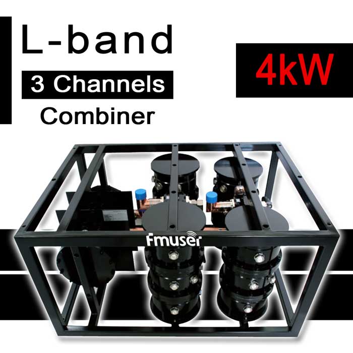
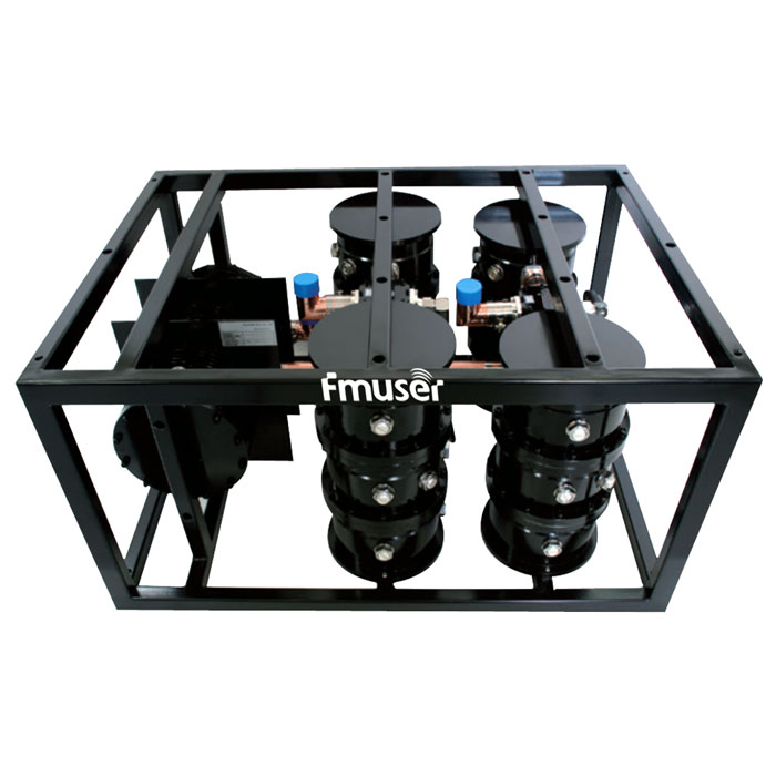
1452-1492 MHz 1 5/8" 6 Cavity 4kW L Band RF Combiner Compact Digital 3 Channel Combiner Solid-state RF Triplexer for TV Station
FEATURES
- Price (USD): Please Contact Us
- Qty (PCS): 1
- Shipping (USD): Please Contact Us
- Total (USD): Please Contact Us
- Shipping Method: DHL, FedEx, UPS, EMS, By Sea, By Air
- Payment: TT(Bank Transfer), Western Union, Paypal, Payoneer
Main Features
- Copper, silver-plated brass, and high-quality aluminum alloy
- Low insertion loss and VSWR
- High isolation
- Compact design
- Dual-mode waveguide filters
- Convenient for multi-frequency integration
- The tailored design, multi-structure, and power combination
- Small size and lightweight
- Customized product
Looking for more transmitter combiners for your broadcast station? Check these!
 |
 |
 |
|
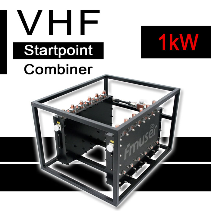
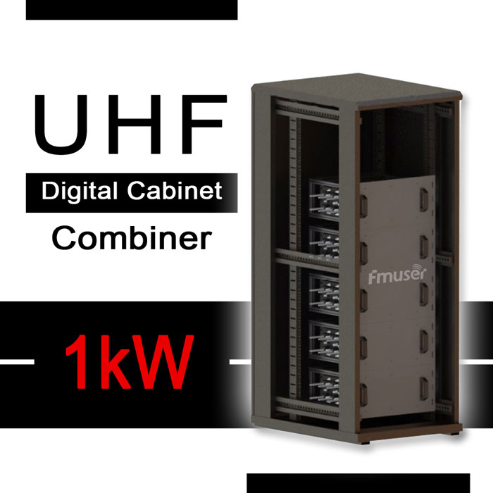
| FM Combiners | VHF Combiners | UHF Combiners | L Band Combiners |
- 4 kW L-Band Digital 3-Channel Combiner x 1PCS
Please Contact Us for More Infomation
|
Terms |
Specs |
|
|---|---|---|
|
Configuration |
Improved CIB |
|
|
Frequency Range |
1452-1492 MHz |
|
|
Min. Frequency Spacing |
1 |
|
|
Max. Input Power |
3 x 1.3 kW |
|
|
VSWR |
≤ 1.15 |
|
|
Insertion loss |
f0 |
≤ 0.60 dB |
|
f0±3.8MHz |
≤ 1.00 dB |
|
|
f0±4.2MHz |
≥ 4 dB |
|
|
f0±6MHz |
≥ 25 dB |
|
|
f0±12MHz |
≥ 40 dB |
|
|
Isolation between inputs |
≥ 60 dB |
|
|
Connectors |
1 5/8" |
|
|
Number of cavities |
6 |
|
|
Dimensions |
995 × 710 × 528 mm |
|
|
Weight |
~ 90 kg |
|
- What is a L-band combiner used for?
- A L-band combiner is a device used to combine multiple signals from different sources, typically in the L-band frequency range, into a single output. Common applications of a L-band combiner include combining multiple satellite signals for satellite television, combining multiple wireless signals for cellular networks, and combining multiple radio signals for broadcast radio stations.
- How do you use a L-band combiner for broadcasting?
- Steps to correctly use a L-band combiner in broadcast station:
1. Connect the input end of the combiner to the transmitter's output.
2. Connect the output end of the combiner to the antenna.
3. Connect the power supply to the combiner.
4. Adjust the combiner's gain control to set the desired signal level.
To avoid problems when using a L-band combiner in broadcast station:
1. Make sure the antenna is properly tuned for the frequencies being used.
2. Ensure that the power supply being used is compatible with the combiner.
3. Double check to make sure all connections are secure and properly terminated.
4. Monitor the signal levels regularly to ensure that there are no unexpected changes or distortions.
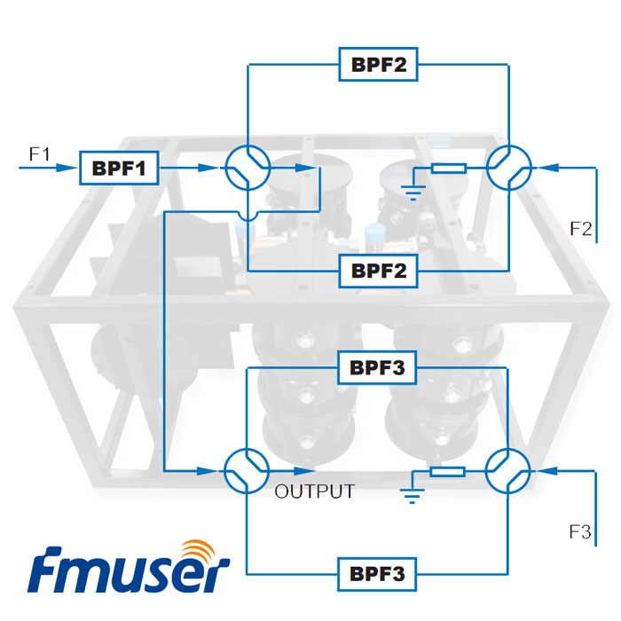
- How does a L-band combiner work?
- A L-band combiner is an electronic device used to combine multiple radio signals into a single output in a broadcast station. The output is usually sent to an antenna for broadcast. The L-band combiner uses a low-noise amplifier (LNA) to amplify the combined signal before sending it to the antenna. The LNA is designed to reduce noise, improve signal-to-noise ratio and boost the overall signal strength. This combination of elements allows for simultaneous transmission of multiple signals without interference or loss of signal quality.
- How many types of L-band combiners are there and what are the differences between them?
- There are three types of L-band combiners: splitter combiners, bandpass combiners, and diplexers. Splitter combiners split the signal into two separate paths and allow for the signal to be combined with another signal. Bandpass combiners combine the signal at a specific frequency, allowing for the signal to be filtered to a specific frequency range. Diplexers combine two different signals at different frequencies and allow them to pass through the same port. The differences between each type of combiner are in the way they combine signals and the frequencies they are designed to work at.
- How do you choose the best L-band combiner?
- When choosing a L-band combiner for a broadcast station, you should consider factors such as the frequency range, insertion loss, isolation, power handling and return loss. Additionally, you should read online reviews and compare the features of different models to ensure that the product meets your station's needs. Finally, you should consult with a technical expert to ensure that you select the best product for your broadcast station.
- How do you correctly connect a L-band combiner into the broadcast system?
- To correctly connect a L-band combiner in a broadcast station, you will need to use coaxial cables to connect the input ports of the combiner to the RF output ports of your broadcast station's transmitters. Then, connect a coaxial cable to the output port of the combiner and connect it to the input port of your antenna. Finally, make sure that all the connections are secure and that the power levels of the transmitters match the power levels of the combiner.
- What equipment is related to a L-band combiner?
- The equipment related to a L-band combiner in a broadcast station includes L-band splitters, high-gain amplifiers, power dividers, coaxial cable, and attenuators.
- What are the most important physical and RF specifications of a L-band combiner?
- The most important physical and RF specifications of a L-band combiner include:
- Frequency Range: 960 MHz to 1710 MHz
- Number of Inputs/Outputs: 4 or more
- Insertion Loss: ≤0.5 dB
- Isolation: ≥30 dB
- VSWR: ≤1.5:1
- Power Handling: ≥200 W
- Connectors: Type N or Type SMA
- How do you correctly maintain a L-band combiner as an engineer?
- 1. Inspect the L-band combiner for any damage or signs of wear and tear.
2. Test all connections to the combiner to ensure a secure electrical connection.
3. Check the power levels of the combiner to make sure it is within the required specifications.
4. Clean the combiner and its components to make sure there is no dust or debris.
5. Check the frequency of the combiner to ensure it is stable and correct.
6. Check the performance of the combiner to make sure it is providing the required level of signal quality.
7. Perform any necessary repairs or adjustments to the L-band combiner.
8. Record all maintenance activities and store the information for future reference.
- How do you repair a L-band combiner if it is not working?
- To repair a L-band combiner, first inspect the combiner for any obvious signs of damage. Check to make sure all cables are properly connected and that there are no loose connections. Check the power connections and make sure they are securely connected. If any of the parts appear to be damaged, they should be replaced.
If the combiner fails to work, the cause of the failure should be identified first. If the failure is due to a broken part, the part can be replaced. Before replacing the part, it is important to ensure that the replacement part is compatible with the combiner. After the new part has been installed, the combiner should be tested to make sure that it is working properly.
- How do you choose the right packaging for a L-band combiner?
- When choosing the right packaging for a L-band combiner, it is important to make sure it is protected from any shock, vibration, or temperature changes that could damage the device. A sturdy, moisture-proof packaging box should be used to protect the combiner from any potential damage during transportation. Make sure to include packing materials such as foam cushions and bubble wrap for extra protection of the device. Additionally, it is important to label the package clearly and ensure it is properly sealed and secured. This will ensure that the combiner arrives safely and free from any damage.
- What material is used for the casing of a L-band combiner?
- The casing of an L-band combiner is generally made of metal, such as aluminum or stainless steel. These materials can affect the performance of the combiner due to their conductive nature, which can lead to a decrease in power transmission efficiency or an increase in signal loss. Additionally, metal casings may also be affected by temperature changes, which can cause them to expand and contract, which could affect the performance of the combiner.
- What is the basic structure of a L-band combiner?
- A L-band combiner typically consists of three major components: a low-pass filter, a power divider, and a high-pass filter. The low-pass filter is responsible for rejecting out-of-band frequencies, while the power divider prevents interference between the input signals. The high-pass filter is responsible for rejecting any signals below the pass band, and is also responsible for determining the attributes and performance of the combiner. Without any of the three structures, the combiner would not be able to function properly.
- Who should be assigned to operate a L-band combiner?
- In a broadcast station, an engineer should be assigned to manage a L-band combiner. This person should possess strong technical skills, familiarity with radio broadcasting equipment, problem-solving abilities, and the ability to work independently.
- How are you?
- I am fine
CONTACT US


FMUSER INTERNATIONAL GROUP LIMITED.
We are always providing our customers with reliable products and considerate services.
If you would like to keep touch with us directly, please go to contact us
-
![Home]()
Home
-
![Tel]()
Tel
-
![Email]()
Email
-
![Contact]()
Contact


