
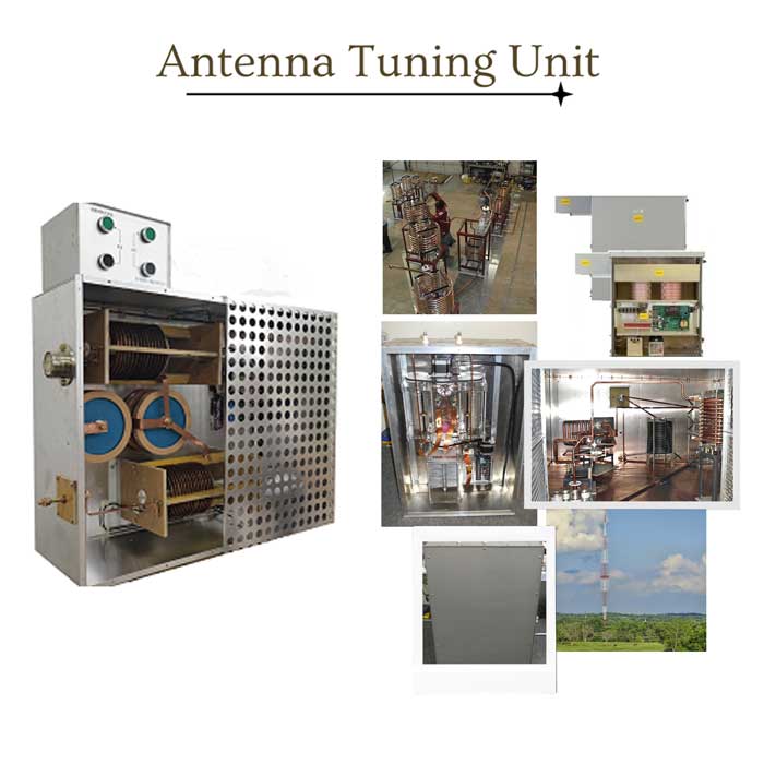
Antenna Tuning Unit
An Antenna Tuning Unit (ATU) is an electronic device that matches the impedance of an antenna system to a transmitter or receiver, optimizing signal efficiency. Impedance varies with frequency, antenna length, and environmental factors.
Unlock Precision & Power: Discover FMUSER’s AM Antenna Tuning Mastery
At FMUSER, we specialize in delivering high-efficiency RF solutions tailored to global broadcasters, system integrators, and industrial operators. This page categorizes our AM ATUs based on power capacity (100W to 50kW+), frequency range (530–1700 kHz), and application-specific designs, simplifying selection for projects ranging from community radio stations to nationwide broadcast networks.
ATUs use adjustable capacitors, inductors, or both to adjust the antenna’s electrical length, ensuring seamless signal transmission.
- Synonyms: Antenna Matcher, Antenna Tuner, Impedance Match Unit, Antenna Coupler, Antenna Matching Network, SWR Tuner/Bridge.
- Typical Placement: Located between the transmitter/receiver and antenna system, ATUs are activated during system power-up to tune the antenna to the desired frequency.
2. Built to Perform: Features That Define FMUSER’s AM ATUs
- Rugged Durability: Weatherproof, industrial-grade enclosures for 24/7 operation.
- Certified Compliance: Meets FCC, CE, and RoHS standards.
- Smart Tuning: Automatic impedance matching with fail-safe protection.
- Scalability: From compact 500W models (ideal for small stations) to 50kW+ systems (for megawatt transmitters).
- Advanced Phase-Locked Loop (PLL) tuning, real-time SWR monitoring, and remote control capabilities.
3. Powering Possibilities: Applications of FMUSER AM Antenna Tuning Units
- AM Radio Broadcasting: Our Solution: Ensures consistent signal clarity even in high-interference environments. FMUSER’s ATUs reduce signal loss by up to 95%, maximizing coverage for broadcasters.
- Emergency Communication Systems: Our Solution: Rapid deployment kits with pre-configured tuning for disaster-resilient networks.
- Military & Defense Radio Networks: Our Solution*: EMI-shielded units with mil-spec durability, trusted for mission-critical operations.
- Educational Campus Radio: Our Solution: Budget-friendly models with plug-and-play setup, enabling low-maintenance student-run stations.
4. Why FMUSER? Competitive Edge for Demanding Projects
- Factory Direct Pricing: Slash costs by up to 30% with no middlemen.
- Instant Shipping: 90% of ATU models in stock, shipped within 48h.
- Turnkey Packages: Antennas, feeders, and ATUs pre-configured for seamless integration.
- Customization & OEM: Modify power ratings, interfaces, or branding for unique needs.
- Proven Expertise: 15+ years serving BBC, Voice of America, and telecom giants in 120+ countries.
5. Smart Buyer’s Checklist: Match Your Needs to the Perfect AM ATU
- Power Handling: Match your transmitter’s output (e.g., 1kW vs. 10kW systems).
- Frequency Compatibility: Ensure coverage of AM band (530–1700 kHz).
- Budget Flexibility: From DIY-friendly $800 units to $25,000+ industrial systems.
- Future-Proofing: Expandable designs for multi-tower setups or phased array upgrades.
-
![FMUSER 200kW AM Antenna Tuning Unit ATU for 200kW AM Transmitter]()
FMUSER 200kW AM Antenna Tuning Unit ATU for 200kW AM Transmitter
Price(USD):Ask for a quotation
Sold:6
-
![FMUSER 100kW AM Antenna Tuning Unit ATU for 100kW AM Transmitter]()
FMUSER 100kW AM Antenna Tuning Unit ATU for 100kW AM Transmitter
Price(USD):Ask for a quotation
Sold:6
-
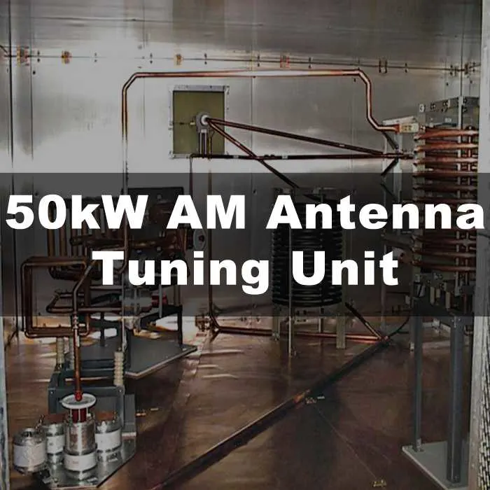
![FMUSER 50kW AM Antenna Tuning Unit ATU for 50000 Watt AM Transmitter]()
FMUSER 50kW AM Antenna Tuning Unit ATU for 50000 Watt AM Transmitter
Price(USD):Ask for a quotation
Sold:6
-
![FMUSER 25kW AM Antenna Tuning Unit ATU for 25kW AM Transmitter]()
FMUSER 25kW AM Antenna Tuning Unit ATU for 25kW AM Transmitter
Price(USD):Ask for a quotation
Sold:6
-
![FMUSER 10kW AM Antenna Tuning Unit ATU for 10kW AM Transmitter]()
FMUSER 10kW AM Antenna Tuning Unit ATU for 10kW AM Transmitter
Price(USD):Ask for a quotation
Sold:6
-
![FMUSER 3kW AM Antenna Tuning Unit ATU for 3kW AM Transmitter]()
-
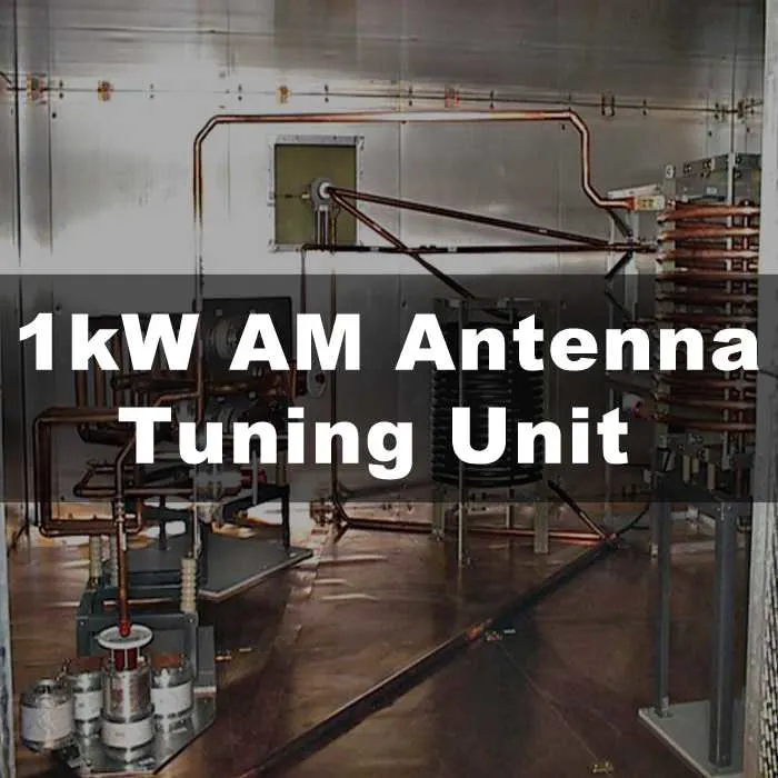
![FMUSER 1kW AM Antenna Tuning Unit ATU for 1kW AM Transmitter]()
-
![FMUSER 50Ω Solid-state Antenna Tuning Unit for 530-1,700 kHz AM Medium Wave Transmitter Station]()
FMUSER 50Ω Solid-state Antenna Tuning Unit for 530-1,700 kHz AM Medium Wave Transmitter Station
Price(USD):Ask for a quotation
Sold:21


- What are the structures of a antenna tuning unit?
- An Antenna Tuning Unit (ATU) can have different structures depending on the specific design and application, but they generally consist of a combination of the following components:
1. Capacitors: These are used to adjust the capacitance of the ATU circuit, which can change the resonance frequency of the overall circuit.
2. Inductors: These are used to adjust the inductance of the ATU circuit, which can also change the resonance frequency of the overall circuit.
3. Variable Resistors: These are used to adjust the resistance of the circuit, which can also have an effect on the resonance frequency of the circuit.
4. Transformers: These components can be used to either step-up or step-down the impedance of the antenna system to match the impedance of the transmitter or receiver.
5. Relays: These are used to connect or disconnect components in the ATU circuit, which can be useful for switching between different frequency bands.
6. Circuit Board: The components of the ATU may be mounted on a circuit board to facilitate assembly.
The specific combination of components used can vary depending on the intended application, desired frequency range, available space, and other factors that may influence the design. The goal of an ATU is to match the impedance of the antenna system to the transmitter or receiver, in order to achieve maximum power transfer and signal quality.
- Why antenna tuning unit is important for broadcasting?
- An antenna tuning unit (ATU) is needed for broadcasting because it helps to optimize the performance of the antenna system, which is critical for achieving high-quality signal transmission and reception. A broadcast antenna system typically needs to operate over a wide frequency range, which can cause the impedance of the antenna to vary significantly. This is particularly true for high-power broadcasting, where even small mismatches in impedance can result in significant signal losses.
By adjusting the components of the ATU, such as the capacitors, inductors, and transformers, the impedance of the antenna can be optimized to match that of the transmitter or receiver. This can help to reduce signal loss and ensure the delivery of high-quality, clear signals to the listeners or viewers.
For a professional broadcasting station, a high-quality ATU is particularly important because it is typically used to transmit signals over long distances and with high power levels. A poorly designed or poorly constructed ATU can introduce a variety of issues that can impact the performance of the broadcast, including signal distortion, interference, and reduced signal strength.
A high-quality ATU designed specifically for broadcasting will typically be designed to withstand harsh environmental conditions, be adjustable across a wide range of frequencies, and be constructed with high-quality components that are selected for their durability and performance. This can help to ensure that the broadcasting signal is as strong and clear as possible, even in challenging situations.
- What are the appliactions of antenna tuning unit?
- Antenna tuning units (ATUs) have a variety of applications in electronics and communication systems. Some of the common applications are:
1. Radio Communication: ATUs are commonly used in amateur radio communication to match the impedance of the antenna to the transmitter or receiver across a wide frequency range. This helps to improve signal quality and minimize signal loss.
2. Television Broadcasting: In television broadcasting, ATUs are used to match the impedance of the broadcast antenna to the transmitter. This ensures that the signal is delivered with the maximum strength and clarity to viewers.
3. FM Broadcasting: ATUs are also used in FM broadcasting to match the impedance of the antenna to the transmitter, particularly in situations where the broadcast frequency is not an exact multiple of the antenna's resonant frequency. This helps to reduce signal loss and improve signal quality.
4. AM Broadcasting: In AM broadcasting, the ATU is used to match the impedance of the antenna system to the transmitter, which helps to reduce signal distortion and maximize signal strength.
5. Aircraft Communication: In aircraft communication systems, ATUs are often used to optimize the performance of the onboard antennas for optimal transmission and reception.
6. Military Communication: ATUs are also used in military communication systems to match the impedance of the antenna to the transmitter or receiver, which helps to improve signal quality and reduce signal loss.
7. Mobile Communications: ATUs are used in mobile communication devices such as cell phones and wireless routers to match the impedance of the antenna to the transmitter. This helps to improve signal quality and minimize power loss.
8. RFID: In radio frequency identification (RFID) systems, ATUs can help to optimize the performance of the antenna by matching its impedance to the RFID reader.
9. Wireless Sensor Networks: In wireless sensor networks (WSNs), ATUs can be used to match the impedance of the sensor nodes to the wireless network, which can improve signal quality and reduce power consumption.
10. Remote Sensing: In remote sensing applications, ATUs are used to match the impedance of the antenna to receive signals from satellites or other remote sensing equipment with high sensitivity and accuracy.
11. Ham Radio: In addition to amateur radio communication, ATUs are often used in ham radio for portable or mobile operations in difficult operating environments where the antenna impedance may vary significantly.
12. Two-way Radios: ATUs are also used in two-way radio systems for industries such as public safety, transportation, and security to optimize the performance of the antenna system in varied environments to ensure clear and reliable communications.
13. Scientific Research: ATUs are used in scientific research to measure and manipulate the electromagnetic fields in a wide range of experiments.
In general, the applications of ATUs are widespread and include any situation where a high-quality signal transmission is required. ATUs can match the impedance of an antenna system to the transmitter or receiver, allowing for optimal signal transmission and reception, reflecting the importance of matching the impedance of the antenna to the transmitter or receiver for optimal signal transmission and reception in many different fields and situations.
- What consists of a complete antenna system along with antenna tuning unit?
- To build a complete antenna system for a radio broadcasting station, different equipment and components are required, depending on the type of broadcasting (UHF, VHF, FM, TV, or AM). Here are some of the essential components of a broadcasting antenna system:
1. Transmitter: It is an electronic device used to generate a modulated radio frequency (RF) signal and send it to the antenna, which then delivers it to the listeners or viewers.
2. Antenna: It is a device that converts electrical energy into electromagnetic (radio) waves that can travel through the air and be received by radio receivers. The design of the antenna depends on the frequency range, power level, and type of broadcasting.
3. Coaxial Cable: It is used to connect the transmitter to the antenna and ensure the efficient transfer of the signal with minimum signal loss and impedance matching.
4. Antenna Tuning Unit (ATU): It is used to match the impedance of the antenna to the transmitter or the receiver. The ATU is particularly useful in cases where the antenna's impedance varies over a wide range of frequencies, as it balances the connection to improve efficiency and power transfer.
5. Combiner/Divider: In broadcasting systems with multiple transmitters or signals, combiners/dividers are used to combine multiple signals into one for transmission on a single antenna.
6. Tower: it is a tall metal structure that supports the antenna and its associated equipment.
7. Transmission Line/Feeder: It is a wire or cable that connects the antenna to the transmitter or receiver, delivering the signal from the antenna to the transmitter/receiver without attenuation or distortion.
8. Lightning Protection: Antenna systems are susceptible to lightning damage, which can cause costly damage. Therefore, lightning protection systems are essential to protect the system from damage during thunderstorms.
9. Monitor and measurement equipment: The signal transmitted can be assessed with the help of various monitoring and measurement equipment, including spectrum analyzers, oscilloscopes, and other signal measurement devices. These instruments ensure that the signal meets technical and regulatory standards.
In conclusion, these are some of the typical equipment needed to build a complete antenna system. The type of equipment used and the configuration of the antenna system are determined by the specific broadcasting needs, including frequency range, power level, and type of broadcasting.
- How many types of antenna tuning unit are there?
- There are several types of antenna tuning units (ATUs) available for use in radio broadcasting and other applications. Let's discuss some of them based on their types and their properties:
1. L-Network Antenna Tuner: The L-network antenna tuner is based on a simple circuit that uses two capacitors and an inductor to match the impedance of the antenna to the transmitter or receiver. L-network ATUs are easy to construct and use, relatively affordable, and provide a high degree of flexibility in terms of impedance matching. However, they have limited performance at high frequencies, and the circuit can be complex to design.
2. T-Network Antenna Tuner: T-network antenna tuners are similar to L-network ATUs but use three capacitance elements along with an inductor to create a 2:1 impedance match. T-network ATUs provide better performance at higher frequencies than L-network ATUs, but they are more expensive and complex to design.
3. Pi-Network Antenna Tuner: Pi-network antenna tuners use three capacitors and two inductors to create a 1.5:1 impedance match. They provide good performance in a wide range of frequencies and offer a better match when compared to L-network and T-network ATUs. However, they are more expensive than L-network and T-network ATUs.
4. Gamma Match Tuner: Gamma match tuners use a gamma match to adjust the feed point impedance of the antenna to match the requirements of the transmitter or receiver. They are highly efficient, and the matching network is simple to design, with little or no loss to the signal. However, they can be expensive to manufacture.
5. Balun Tuner: Balun tuners use a balun transformer to balance the impedance of the antenna to the requirements of the transmitter or receiver. They provide excellent impedance matching and are highly efficient, with no or little loss. However, they can be expensive to install and maintain.
6. Auto-Tuner/Smart Tuner: Auto-tuner or smart tuner uses a microprocessor to adjust the matching network automatically by measuring the impedance of the antenna in real-time, making them convenient to use. They offer high-performance in a wide range of frequencies, but they can be expensive to purchase and require a power source to operate.
7. Reactance Tuner: Reactance tuners use a variable capacitor and inductor to adjust the impedance of the antenna system. They are simple and relatively low-cost but may not be suitable for high-power applications.
8. Duplexer: A duplexer is a device used to allow a single antenna to be used for both transmitting and receiving. They are commonly used in radio communication applications, but they can be expensive and require skilled installation.
9. Transmatch Antenna Tuner: Transmatch tuners use a high-voltage variable capacitor and inductor to match the transmitter's output to the antenna system. They are highly efficient, but the high-voltage components can be expensive to manufacture and maintain.
10. Meanderline Antenna Tuner: This is a new type of antenna tuner that uses a meanderline structure, which is a type of transmission line that can be etched on a substrate. Meanderline ATUs provide excellent performance and are lightweight and low-profile, but they may be expensive to manufacture.
11. Network Analyzer: While not technically an ATU, a network analyzer can be used to evaluate the performance of an antenna system and make adjustments as necessary. Network analyzers can provide valuable information about the system's impedance, SWR, and other parameters, but they can be expensive and require specialized training to operate effectively.
In summary, the choice of the antenna tuner depends on the particular application and signal requirements. The L-network ATU is simple, affordable, and flexible, while other types provide better matching performance across different frequency ranges. Gamma match tuners are highly efficient, while auto-tuners are convenient but expensive. All ATUs require installation, maintenance, and repairment depending on the environment and the specific needs of the antenna system, choosing the right ATU can help maximize the antenna system's performance, ensuring reliable, high-quality signal transmission and reception.
- What are terminologies related to antenna tuning unit?
- Here are some of the terminologies related to antenna tuning units:
1. Impedance: Impedance is the resistance that an antenna system offers to the flow of current when a voltage is applied. The value of impedance is measured in Ohms.
2. Matching Network: A matching network is a device that adjusts the impedance of a source or load to optimize the transfer of power.
3. SWR: SWR (Standing Wave Ratio) is the ratio of the maximum amplitude of a standing wave to the minimum amplitude of the same wave. SWR can be used to determine the efficiency of an antenna system, with lower ratios indicating more efficient systems.
4. Reflection Coefficient: The reflection coefficient is the amount of power that is reflected when a signal encounters an impedance mismatch. It is a measure of the efficiency of the antenna system and is expressed as a decimal or percentage.
5. Bandwidth: Bandwidth is the range of frequencies over which an antenna system can operate efficiently. The bandwidth depends on various factors such as the type of antenna, its impedance, and the matching network configuration.
6. Q-Factor: Q-Factor is a measure of the efficiency of a resonant antenna system. It indicates the sharpness of the resonance curve and the degree of energy loss as a signal is transferred through the system.
7. Inductance: Inductance is a property of an electrical circuit that opposes changes in the current flow. It is measured in Henries and is an essential component of an ATU.
8. Capacitance: Capacitance is a property of an electrical circuit that stores electrical charge. It is measured in farads and is another critical component of an ATU.
9. Resistive Matching: Resistive matching is the process of matching the resistance of the antenna to the system's transmitter or receiver output. It involves adjusting the ATU components to minimize power losses.
10. Inductive Matching: Inductive matching is the process of matching the reactance of the antenna system to the transmitter or receiver output. It involves adjusting the ATU's inductance to provide optimal impedance matching.
11. VSWR: VSWR (Voltage Standing Wave Ratio) is similar to SWR but is expressed in terms of voltage instead of power. It is a measure of the efficiency of an RF transmission line or antenna system.
12. Insertion Loss: Insertion loss is the loss that occurs when a signal travels through a device or circuit, such as an antenna tuner. It is measured in decibels (dB) and is an important parameter to consider when selecting an ATU.
13. Tuning Range: The tuning range is the range of frequencies over which the ATU can provide adequate impedance matching. The range varies depending on the type of antenna tuner and the frequency range of the antenna system.
14. Power Rating: The power rating is the maximum power that the ATU can handle without damage or degradation in performance. It is typically measured in watts and is an important consideration when selecting an ATU for a specific application.
15. Noise Figure: Noise figure is a measure of the noise performance of an ATU. It indicates the amount of noise that is introduced into the signal as it passes through the ATU and is typically expressed in decibels.
16. Phase Shift: Phase shift is the time delay between the input and output signal in an ATU. It can affect the signal’s amplitude and phase characteristics and is an important consideration when designing and selecting an ATU.
17. Reflection Loss: Reflection loss is the amount of power that is reflected back to the transmitter due to an impedance mismatch in the antenna system. It is typically expressed in decibels and can affect the efficiency and performance of the system.
In summary, these terminologies are essential to understanding antenna tuning units' functionality and performance. They help define the impedance and bandwidth requirements of the antenna system, the efficiency of the ATU components, and the overall performance of the system. By optimizing these parameters, the antenna system can achieve maximum performance and provide reliable, high-quality signal transmission and reception.
- What are most important specifications of antenna tuning unit?
- The most important physical and RF specifications of an antenna tuning unit (ATU) will depend on the specific application and system requirements. However, here are some of the critical physical and RF specifications that are commonly used to evaluate an ATU:
1. Impedance Matching Range: The impedance matching range is the range of impedance values over which the ATU can provide adequate impedance matching. It is essential to select an ATU that can match the impedance of the antenna system to the transmitter or receiver output.
2. Power Handling Capacity: The power handling capacity is the maximum power that the ATU can handle without damage or degradation in performance. It is crucial to select an ATU that can handle the power level of the transmitter or receiver without introducing signal distortion or other problems.
3. Frequency Range: The frequency range is the range of frequencies over which the ATU can operate effectively. It is essential to select an ATU that can operate within the frequency range of the antenna system and transmitter or receiver.
4. VSWR: The VSWR (Voltage Standing Wave Ratio) is a measure of the efficiency of an RF transmission line or antenna system. A high VSWR indicates an impedance mismatch and can result in signal distortion or attenuation.
5. Insertion Loss: The insertion loss is the loss that occurs when a signal passes through the ATU. It is essential to select an ATU with low insertion loss to minimize signal attenuation and distortion.
6. Tuning Speed: The tuning speed is the time it takes for the ATU to match the impedance of the antenna system to the transmitter or receiver output. The tuning speed should be fast enough to keep up with the signal's frequency and power variations.
7. Noise Figure: The noise figure is a measure of the noise performance of an ATU. It indicates the amount of noise that is introduced into the signal as it passes through the ATU. The noise figure should be as low as possible to minimize signal distortion and noise.
8. Size and Weight: The size and weight of the ATU may be significant considerations, depending on the specific application and installation requirements. Small, lightweight ATUs may be preferable in some cases, while larger, more robust units may be necessary for high-power applications.
In summary, these physical and RF specifications are significant considerations when selecting an antenna tuning unit. By selecting an ATU that meets these specifications, the antenna system can achieve maximum performance and provide reliable, high-quality signal transmission and reception.
- What are the differences of antenna tuning unit used in different broadast station?
- The antenna tuning unit (ATU) used in different broadcast stations can vary significantly depending on the specific application and frequency range. Here are some differences between ATUs used in different broadcast stations:
1. UHF/VHF Broadcast Stations: UHF/VHF broadcast stations typically use ATUs that are designed for a specific frequency range, such as 350-520 MHz for VHF and 470-890 MHz for UHF. These ATUs are usually built into the antenna structure or mounted very close to the antenna. They may use a variety of impedance-matching techniques, such as a quarter-wave transformer, gamma match, or balun. The advantages of using a dedicated ATU for UHF/VHF frequencies include improved signal quality and efficiency, while some disadvantages include the high cost and specialized installation and maintenance requirements.
2. TV Broadcast Stations: TV broadcast stations use ATUs that are optimized for a specific channel frequency, such as 2-13 for VHF and 14-51 for UHF. These ATUs may use different techniques to match the impedance, such as a latching relay, automatic matching network, or fixed matching network. They are typically mounted in a separate equipment room or building and are connected to the transmitter via a coaxial cable. The advantages of using a TV-specific ATU include improved signal quality and compatibility with the transmitter, while the disadvantages may include higher costs and more complex installation and maintenance requirements.
3. AM Broadcast Stations: AM broadcast stations use ATUs that are designed to match the impedance of the antenna to the transmitter output impedance, which is typically 50 Ohms. These ATUs may use various techniques, such as a pi-network, L-network, or T-network. They may also include filtering components to remove unwanted frequencies. They are usually located in a separate equipment room or building and are connected to the transmitter via a transmission line, such as open wire or coaxial cable. The advantages of using an AM-specific ATU include improved signal quality and compatibility with the transmitter, while the disadvantages may include higher costs and more complex installation and maintenance requirements.
4. FM Broadcast Stations: FM broadcast stations use ATUs that are optimized for a specific frequency band, such as 88-108 MHz. These ATUs may use different techniques to match the impedance, such as a stub tuner, butterfly capacitor, or folded dipole antenna. They may also include filtering components to remove unwanted frequencies. They are typically located in a separate equipment room or building and are connected to the transmitter via a transmission line, such as coaxial cable or waveguide. The advantages of using an FM-specific ATU include improved signal quality and compatibility with the transmitter, while the disadvantages may include higher costs and more specialized installation and maintenance requirements.
In conclusion, the choice of ATU for a broadcast station depends on several factors, including the frequency range, transmitter power, signal quality, and installation and maintenance requirements. By selecting the appropriate ATU and optimizing its performance, the broadcast station can achieve maximum signal quality and reliability, ensuring high-quality signal transmission and reception.
- How to choose antenna tuning unit for different broadcast stations?
- Choosing the best antenna tuning unit (ATU) for a radio broadcasting station requires careful consideration of the specific application, frequency range, transmitter power, and other performance requirements. Here are some guidelines for selecting the best ATU for different broadcasting applications:
1. UHF Broadcasting Station: When choosing an ATU for a UHF broadcasting station, look for ATUs that are designed for the frequency range used by the station, which is typically 470-890 MHz. The ATU should be optimized for low insertion loss and high power handling capacity to minimize signal distortion and ensure reliable transmission. A dedicated ATU that is built into the antenna structure or mounted close to the antenna may be the best choice for a UHF broadcasting station.
2. VHF Broadcasting Station: For a VHF broadcasting station, choose an ATU that is optimized for the specific VHF frequency range used by the station, which is typically 174-230 MHz. The ATU should have a low insertion loss and a high power handling capacity to ensure reliable transmission. A dedicated ATU that is built into the antenna structure or mounted close to the antenna may be the best choice for a VHF broadcasting station.
3. FM Radio Station: For an FM radio station, choose an ATU that is optimized for the specific frequency band used by the station, which is typically 88-108 MHz. The ATU should have a low insertion loss and a high power handling capacity to minimize signal distortion and ensure reliable transmission. A dedicated ATU that is located in a separate equipment room or building and connected to the transmitter via a transmission line, such as a coaxial cable, may be the best choice for an FM radio station.
4. TV Broadcasting Station: When selecting an ATU for a TV broadcasting station, choose an ATU that is optimized for the specific channel frequency used by the station, which is typically 2-13 for VHF and 14-51 for UHF. The ATU should have a low insertion loss and a high power handling capacity to ensure reliable transmission. A dedicated ATU that is located in a separate equipment room or building and connected to the transmitter via a coaxial cable may be the best option for a TV broadcasting station.
5. AM Broadcasting Station: For an AM broadcasting station, choose an ATU that is optimized for the specific frequency range used by the station, which is typically 530-1710 kHz. The ATU should be designed to match the impedance of the antenna to the transmitter output impedance, which is typically 50 Ohms. A pi-network or T-network ATU may be the best choice for an AM broadcasting station.
In conclusion, choosing the best ATU for a radio broadcasting station requires careful consideration of the specific frequency range, power handling capacity, insertion loss, and impedance matching requirements. By selecting the appropriate ATU and optimizing its performance, the broadcasting station can achieve maximum signal quality and reliability, ensuring high-quality signal transmission and reception.
- How antenna tuning unit is made and installed?
- Here is an overview of the process of producing and installing an Antenna Tuning Unit (ATU) inside a broadcasting station:
1. Design and Engineering: The process begins with the design and engineering phase, where the specifications and requirements of the ATU are determined. This includes the frequency range, power handling capacity, tuning range, and other parameters.
2. Component Sourcing: After the design phase, components such as capacitors, inductors, and resistors are sourced from trusted suppliers to ensure high quality.
3. Printed Circuit Board (PCB) Design and Manufacturing: The circuit board is designed based on the design requirements of the ATU and is fabricated by automated machinery.
4. Assembly: The circuit board and other components including integrated circuits are assembled by expert technicians in precise steps. The board is electrically tested to ensure functionality.
5. Tuning the ATU: The ATU is then tuned for optimal performance in the manufacturing environment.
6. Quality Control: A final inspection by quality control personnel is conducted to ensure that the ATU meets all specifications.
7. Manufacturing and Packaging: After passing the quality control check, the ATUs are manufactured in volume and packaged for shipment.
8. Shipping and Delivery: The ATUs are then shipped to the broadcasting station or distributor.
9. Installation and Integration: Following delivery, the ATUs are installed, integrated, and connected to the broadcast transmitter. This process may involve replacing old components or installing the ATU into the station's existing transmission network.
10. Testing and Configuration: The ATU is then tested to ensure that it operates correctly and provides the optimal performance required for its application. It is also configured to optimize its tuning and impedance matching capability.
11. Fine-tuning and Optimization: After installation, the ATU's impedance matching is tuned and optimized to ensure that it matches the output impedance of the transmitter and antenna system, maximizing the signal output power levels.
12. FCC Certification: Finally, the ATU is certified by appropriate authorities, such as the FCC, ensuring that it meets the regulatory standards for frequency allocations, maximum power levels, and other parameters.
In conclusion, the antenna tuning unit (ATU) is an essential device in broadcasting stations that requires precise engineering and manufacturing to ensure optimal performance. The process of producing and installing an ATU involves many intricate steps, from design and engineering to testing, certification, installation, and optimization. All these stages must meet the highest standards of function and safety to produce high-quality and interference-free signals that reach the intended audience.
- How do you correctly maintain a antenna tuning unit?
- Maintaining the antenna tuning unit (ATU) in a broadcast station is essential to keep the equipment working efficiently and producing high-quality signals. Here are some tips on how to correctly maintain an ATU:
1. Inspection: Regularly inspect the ATU for signs of damage, wear and tear, and any signs of corrosion or rust. Check the wiring, connectors, and ground wire for signs of oxidation, and damage.
2. Cleaning: Keep the ATU clean by wiping it down regularly using a clean, dry cloth. You can also use a soft-bristled brush to remove any dust and dirt that may accumulate on the surface of the ATU.
3. Power monitoring: Monitor the power levels to ensure that the ATU is not damaged by too much power. Proper power monitoring can also prevent emitter damage, which can significantly impact the performance of the ATU.
4. Regular Tuning: The Tuning unit needs occasional fine-tuning for optimal performance to maintain the desired impedance near the matching and tuning frequency ranges.
5. Weather Protection: The ATU is housed in a weatherproof shelter for protection from weather elements such as rain, dust, and airborne debris, which can damage its internal components. Proper weather protection can prevent damage and ensure that the ATU functions properly over time.
6. Grounding: Ensure that the grounding system is effective and consistent to discharge any oscillation or static build-ups. This ensures a stable RF field, which is essential for the proper operation of the ATU.
7. Documentation: Maintain proper documentation for critical operations such as regular maintenance, changes in the frequency, or replacement of the unit to keep track of the ATU's status over time.
By following proper maintenance procedures, the ATU will function reliably and produce high-quality and interference-free radio signals that reach the intended audience. Regular inspections, tuning, cleaning, proper documentation, power monitoring, effective grounding, and weather protection ensure optimal performance and extend the ATU lifespan.
- How do you repair a antenna tuning unit if it fails to work?
- If an antenna tuning unit (ATU) fails to function properly, you can follow these steps to repair the unit:
1. Identify the Problem: The first step is to identify what specific part of the ATU is malfunctioning. You can do this by observing the system's behavior, and conducting a series of tests with a multimeter to determine the root cause of the problem.
2. Replace the Faulty Component: Once you have identified the faulty component, replace it and test the ATU again to see if it is functioning correctly. Common replacement parts include fuses, capacitors, inductors, diodes, or transistors.
3. Check the Power Supply: Ensure that the ATU is receiving power from the source, such as the AC power supply, and that the voltage and current are within the ATU’s specified range.
4. Check Connections: Examine the wiring of the ATU, including the ground connections, signal and power inputs, and outputs, and any tamper-proof seals. Tighten any loose terminals or connections and retest the ATU.
5. Cleaning: The ATU's components may accumulate dust, debris, or other contaminants over time, leading to short circuits or other malfunction. Use a brush and alcohol to clean these components and remove any corrosion from connectors or ground wires.
6. Repair the Printed Circuit Board (PCB): If the ATU's PCB is damaged, repair or replace it. PCBs can be repaired by a professional technician who is skilled in repairing complex electronics.
7. Professional Repair: For advanced repairs or more complex issues, it may be necessary to consult with a trained professional. They have the expertise and tools to diagnose and repair defects beyond the scope of the average technician.
In conclusion, repairing an ATU requires a methodical and thorough approach. It involves identifying the problem, replacing faulty components, examining connections, cleaning, and sometimes repairing the PCB. With proper care and repairs, an ATU can provide years of reliable service, improving signal quality while saving repair costs and downtime.
CONTACT US


FMUSER INTERNATIONAL GROUP LIMITED.
We are always providing our customers with reliable products and considerate services.
If you would like to keep touch with us directly, please go to contact us
-
![Home]()
Home
-
![Tel]()
Tel
-
![Email]()
Email
-
![Contact]()
Contact


