
FM Broadcast Antennas
FMUSER’s FM broadcast antennas are critical for delivering high-fidelity, reliable radio transmission across commercial, community, and emergency broadcasting systems.
1. FM Antennas Engineered for Every Frequency & Power Demand
As a leader in RF innovation, FMUSER specializes in designing antennas tailored for precise frequency ranges (87–108 MHz), power capacities, and deployment scenarios. This page simplifies your selection process by categorizing antennas based on wave type (1/2 Wave, 1/4 Wave), polarization (circular/vertical), panel/bay configurations, and application-specific designs, ensuring professionals find the perfect match for radio stations, mobile setups, or large-scale transmitter networks.
2. Key Features
- Robust Durability: Stainless steel/weatherproof aluminum builds for outdoor resilience.
- Certified Efficiency: Compliance with FCC/CE standards for seamless global deployment.
- Scalable Power Handling: From entry-level GP100 (1/4 Wave) to high-power 8-Bay DV1 arrays (up to 10kW+).
- Advanced Tech: Dual dipole panels for interference resistance; circular polarization for superior signal coverage.
- Universal Frequency: Optimized for 87–108 MHz bands, compatible with all FM transmitters.
3. Diverse Applications of FMUSER’s FM Broadcast Antennas
1) Commercial Radio Broadcasting
FMUSER’s High Gain Circular Polarized Antenna (CP100) and Eight-Bay DV1 Antenna are specifically designed for large-scale radio stations requiring unwavering signal clarity and expansive coverage. The CP100 leverages circular polarization technology to deliver uniform signal distribution across diverse terrains, minimizing multipath interference and dropouts common in urban areas. Coupled with the Eight-Bay DV1 Dipole Array, which provides directional beam focusing and power handling up to 10kW+, broadcasters achieve FCC-compliant transmission for high-power FM/HD Radio multiplexing. These antennas are engineered for tower installations, ensuring reliable 24/7 operation under extreme weather, making them ideal for national networks or metropolitan stations aiming to reach millions of listeners with crystal-clear audio.
2) Mobile/Portable FM Stations
The FMUSER CA200 Car Antenna with Suction Pad revolutionizes mobile broadcasting, enabling on-the-go transmission for emergency response teams, sports commentators, or pop-up FM stations. Its compact, lightweight design features a robust suction base for rapid deployment on vehicle rooftops, coupled with a wide 87–108 MHz bandwidth to maintain stable connectivity even in motion. The CA200’s omnidirectional radiation pattern ensures consistent signal coverage within a 15–30 km radius, making it indispensable for disaster recovery broadcasts, live event coverage, or temporary community radio setups. With a corrosion-resistant build and tool-free installation, this antenna eliminates downtime, empowering mobile operators to deliver critical information without compromising on portability or durability.
3) Community Low-Power FM (LPFM)
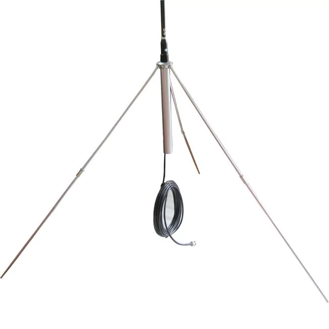
FMUSER’s GP100 1/4 Wave Ground Plane Antenna offers an affordable, space-efficient solution for community-driven stations, such as college radio, religious organizations, or local news hubs. Optimized for low-power transmission (up to 500W), this antenna features a streamlined mast-mounted design that fits small rooftops or tower spaces while maintaining a 360° coverage pattern. Its galvanized steel construction ensures long-term durability in suburban or rural environments, and the impedance-matched elements reduce VSWR for efficient energy use. By eliminating complex installation requirements, the GP100 allows grassroots broadcasters to focus on content creation rather than technical hurdles, fostering hyper-local engagement at a fraction of traditional infrastructure costs.
4) High-Power Transmitter Sites
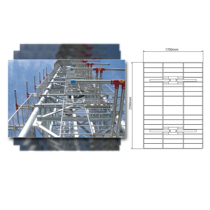
For industrial-grade broadcasting hubs, FMUSER’s Eight-Bay DV1 Dipole Array and High Power Dual Dipole Panel Antenna provide unmatched scalability and reliability. The Eight-Bay DV1 system combines phase-adjustable dipole modules to create precise directional patterns, ideal for targeting densely populated regions or avoiding interference from adjacent channels. Capable of handling up to 12kW, it supports multiplexed digital/analog signals without distortion. Meanwhile, the High Power Dual Dipole Panel Antenna features dual RF inputs for redundancy and power combining, paired with a ±15° adjustable elevation beam for terrain-specific optimization. Both solutions utilize industrial-grade aluminum and stainless steel hardware, making them suitable for harsh environments like coastal transmission sites or high-altitude towers, ensuring uninterrupted service for national broadcasters and telecom operators.
4. Why Choose FMUSER?
- Factory Direct Pricing: Save 30–50% vs. middleman distributors.
- Always In-Stock: Fast global shipment (3–5 days for standard models).
- Turnkey Solutions: Pre-configured antenna systems + free technical support.
- Customization/OEM: Modify specs (gain, connectors) for unique projects.
- Proven Expertise: Trusted by BBC affiliates, emergency networks, and 10,000+ global clients.
5. Buying Guide
- Evaluate Power Needs: Match antenna wattage (e.g., GP200 for 5kW) to your transmitter.
- Check Mounting Requirements: Suction-based (CA200) vs. mast-mounted (DV1 arrays).
- Budget Alignment: Balance upfront costs (GP100) vs. long-term ROI (high-gain CP100).
-
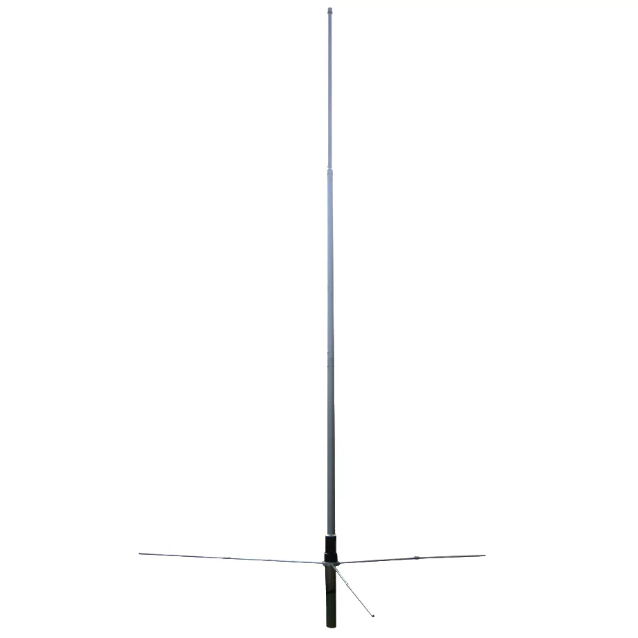
![FMUSER GP200 1/2 Wave Ground Plane FM Antenna]()
-
![FMUSER GP100 1/4 Wave Ground Plane FM Antenna]()
-
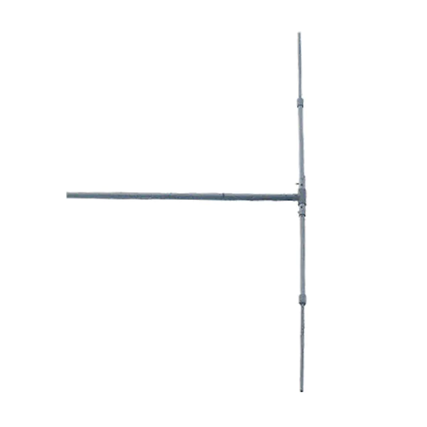
![FMUSER DP100 1/2 Wave FM Dipole Antenna]()
-
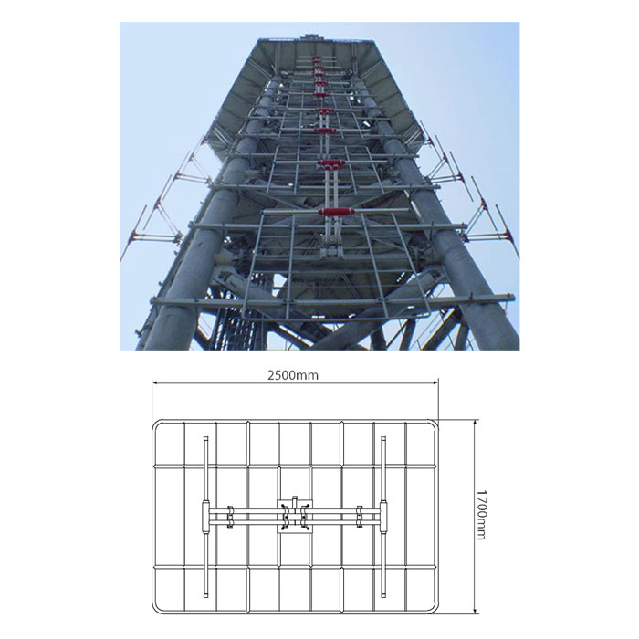
![FMUSER High Power FM Dual Dipole Panel Antenna 87 MHz to 108 MHz (dual RF connector) for FM Antenna System]()
Price(USD):Ask for a quotation
Sold:165
-
![FMUSER High Gain FM Dual Dipole Panel Antenna 87 MHz to 108 MHz for FM Antenna System]()
FMUSER High Gain FM Dual Dipole Panel Antenna 87 MHz to 108 MHz for FM Antenna System
Price(USD):Ask for a quotation
Sold:549
-
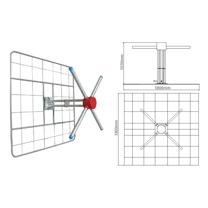
![FMUSER High Gain Circular Polarized Antenna 87 MHz to 108 MHz for FM Transmitter Station]()
FMUSER High Gain Circular Polarized Antenna 87 MHz to 108 MHz for FM Transmitter Station
Price(USD):Ask for a quotation
Sold:348
-
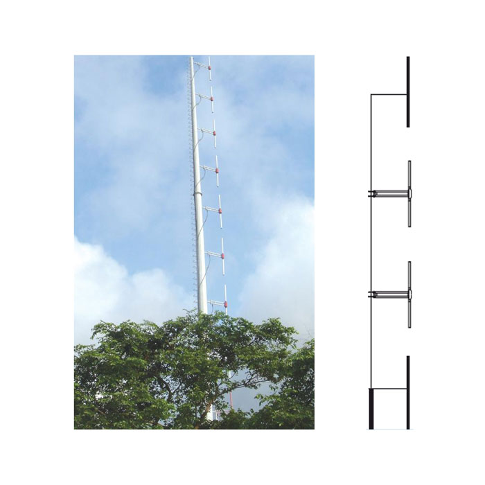
![FMUSER FM Vertical Single Dipole Antenna 87 MHz to 108 MHz for FM Transmitter Station]()
FMUSER FM Vertical Single Dipole Antenna 87 MHz to 108 MHz for FM Transmitter Station
Price(USD):Contact for more
Sold:1,384
-
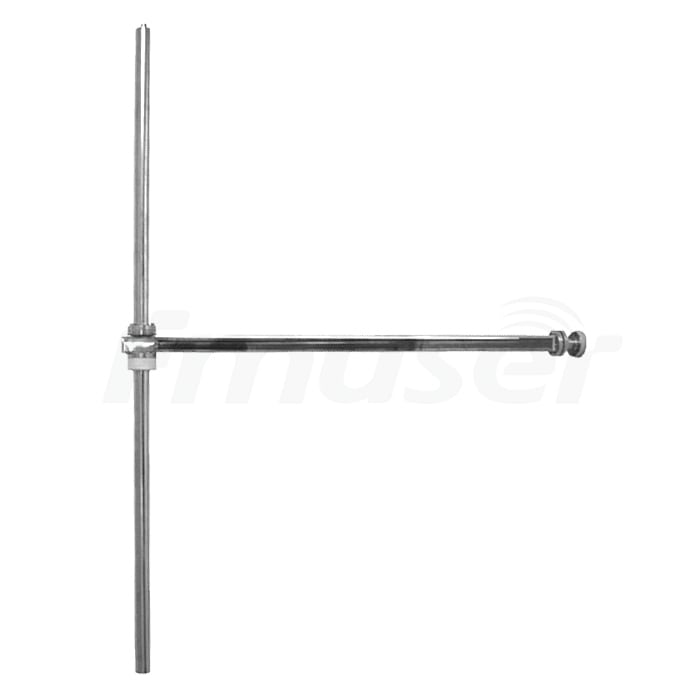
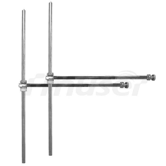
![FMUSER FM-DV1 One Bay FM Transmitter Antenna 1 Bay FM Dipole Antenna for Sale]()
FMUSER FM-DV1 One Bay FM Transmitter Antenna 1 Bay FM Dipole Antenna for Sale
Price(USD):Ask for a quotation
Sold:41
-
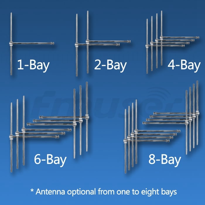
![FMUSER FM-DV1 1/2/4/6/8 Bay Dipole FM Antenna]()
-
![FMUSER FM-DV1 Two Bay FM Transmitter Antenna 2 Bay FM Dipole Antenna for Sale]()
-
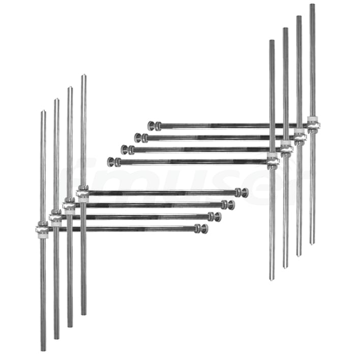
![FMUSER FM-DV1 Eight Bay FM Transmitter Antenna 8 Bay FM Dipole Antenna for Sale]()
FMUSER FM-DV1 Eight Bay FM Transmitter Antenna 8 Bay FM Dipole Antenna for Sale
Price(USD):Ask for a quotation
Sold:19
-
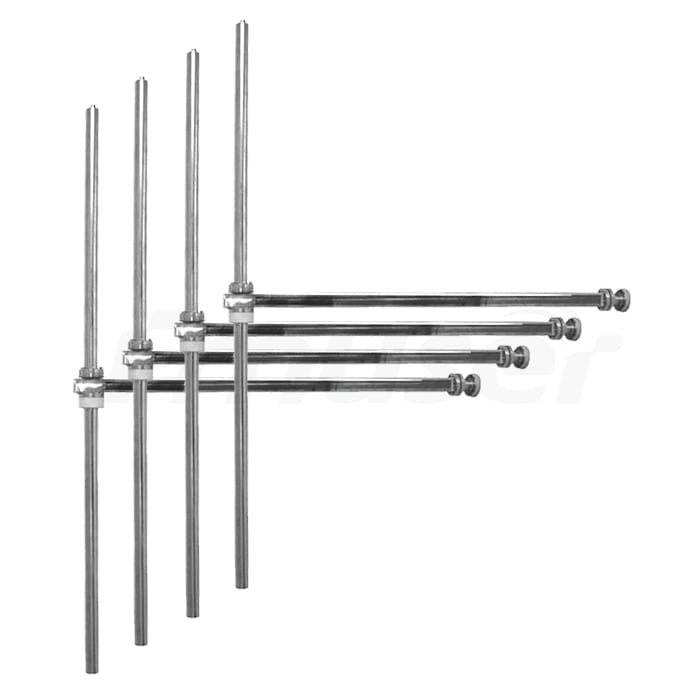
![FMUSER FM-DV1 Four Bay FM Transmitter Antenna 4 Bay FM Dipole Antenna for Sale]()
-
![FMUSER FM-DV1 Six Bay FM Transmitter Antenna 6 Bay FM Dipole Antenna for Sale]()
FMUSER FM-DV1 Six Bay FM Transmitter Antenna 6 Bay FM Dipole Antenna for Sale
Price(USD):3765
Sold:98
-
![FMUSER CP100 Polarized FM Antenna]()
FMUSER CP100 Polarized FM Antenna
Price(USD):Ask for a quotation
Sold:1
FMUSER CP100 circular polarized FM antenna is a new antenna designed for FM radio stations, using with FM transmitters up to 300~500watt.
-
![FMUSER CA200 FM Antenna With Suction Pad for Car]()
FMUSER CA200 FM Antenna With Suction Pad for Car
Price(USD):Ask for a quotation
Sold:1
The FMUSER CA200 is a high-quality FM Antenna for the car.
- What are the structures of a FM broadcast antenna?
- A typical FM broadcast antenna consists of several key structural elements. These may include the following:
1. Support structure: This is the main tower or mast that supports the antenna and keeps it aloft. It is typically made of high-strength materials such as steel and may be several meters tall.
2. Antenna elements: These are the metal rods or wires that form the actual transmitting element of the antenna. They are arranged in a specific pattern to optimize signal strength and coverage.
3. Feedline: This is the cable that carries the electrical signal from the transmitter to the antenna. It is often made of coaxial cable, which has high shielding to prevent interference from other signals.
4. Balun: This is a device that matches the impedance of the feedline to that of the antenna, allowing for efficient signal transfer and reducing signal loss.
5. Grounding system: This is a set of metal rods or wires that is buried in the ground around the antenna tower. It serves to ground the antenna and reduce the risk of lightning strikes or other electrical hazards.
6. Transmission line: This is the cable that connects the antenna to the transmitter power amplifier. It is often made of high-strength copper wire or coaxial cable, and may be several meters long.
Together, these elements work together to create a powerful and efficient FM broadcast antenna that can transmit radio signals over long distances and to a large audience.
- How to install an FM radio broadcast antenna on a radio tower?
- The process of installing an FM broadcast antenna on a radio tower typically involves several steps, including the following:
1. Site preparation: Before the installation process can begin, the site must be surveyed and prepared to ensure that it is stable, secure, and meets the necessary regulations and safety requirements.
2. Tower inspection: The tower structure must be inspected to ensure that it is stable and can safely support the weight and wind load of the antenna and cabling components.
3. Antenna installation: The antenna elements are attached to the support structure of the tower and carefully aligned according to the manufacturer's specifications and any regulatory requirements.
4. Cable installation: The feedline and transmission line are installed and securely attached to the tower and antenna elements, taking care to use high-quality materials and proper cable management techniques.
5. Balun installation: The balun is installed and securely attached to the feedline, ensuring that it is properly matched to the impedance of the antenna elements.
6. Grounding system installation: The grounding system is installed and connected to the tower and any other required grounding points, including the transmitter building, to ensure that the antenna is properly grounded and protected from electrical hazards.
During the installation process, it is important to follow all relevant safety guidelines and regulatory requirements, and to use high-quality materials and proper installation techniques to ensure the reliability and safety of the antenna system. Additionally, it is important to conduct regular inspections and maintenance of the system to ensure that it continues to operate effectively and safely over time.
- What are common types of radio tower for FM broadcast transmitter installation?
- There are several types of radio towers that can be used for FM broadcast antenna installation, including the following:
1. Guyed towers: These are tall towers that use guy wires to provide additional support and stability. They are typically less expensive to construct than self-supporting towers, but require more installation space and can be more difficult to install and maintain.
2. Self-supporting towers: These towers are designed to be freestanding and rely on their own structural integrity to support the antenna and other components. They can be more expensive to construct than guyed towers, but require less installation space and can be easier to install and maintain.
3. Monopoles: These are single-pole structures that are commonly used in urban or suburban areas where space is limited. They are typically less expensive than self-supporting towers but may have lower height limits and load-bearing capacities.
4. Water towers: In some cases, water towers can be used as the support structure for FM broadcast antennas. They can be less expensive than other tower types, but may require significant modification to support the additional weight and wind load.
The number of types of radio towers varies depending on different factors, but the above-mentioned types are the most common ones.
In terms of producing prices, structure, configuration, height, allowing installation spaces for FM broadcast antenna, size, and certifications needed for antenna installation, these factors vary depending on the type of tower and local regulations. Generally, self-supporting towers and monopoles are more expensive than guyed towers, but they require less installation space and may have higher load-bearing capacities. The height of the tower is determined by the intended coverage area and the zoning regulations in the area. Installation space requirements can vary significantly by tower type and may be regulated by local building codes. Certification requirements for antenna installation may also vary by location and may include both structural engineering certification and electrical engineering certification.
In terms of tower construction, self-constructed towers can be an option for small scale applications, but a professional tower installation company is generally recommended for larger installations. Renting a tower may also be an option, depending on the needs of the broadcaster and the availability of suitable tower structures in the area.
- How many kinds of FM broadcast antennas are there based on polarization methods
-
FM slot antenna
A slot antenna is a type of directional antenna that is best suited for use in areas where there is a strong signal. The antenna works by creating a slot in a conducting material, and the slot size and shape determine the frequency response of the antenna. Slot antennas have a vertical polarization and are directional, which means they need to be pointed in the direction of the transmitter. They are generally used for medium to high power applications.
FM slot antennas are a type of flat panel antenna used for FM radio broadcasting and reception. They work by transmitting and receiving radio signals through a slot in a metal plate. Advantages of slot antennas include their low profile design and wide bandwidth. Disadvantages include their limited gain and directional coverage. They can be used in both single and multi-bay configurations, and are typically connected via an N-type coax connector.Terms Specifications Advantages Directional, high power handling capacity, low noise receptionDisadvantages Directional, requires precise aiming, no flexibility in frequency tuningEquipment Needed Coaxial cable, mounting bracket, RF amplifier Bay Configuration Single bay only Coax Connector type Type N or 7/16 DIN Frequency Range 88-108 MHz Power-Handling Capacity Up to 1 kW Directionality Directional Antenna Gain 6-8 dBi Price $500-$1,000 Structure Flat, rectangular Installation Height 10-20 feet above ground level Applications Broadcast radio Installation Requirements Must be precisely aimed, requires a clear line of sight to the transmitterMaintenance Periodic cleaning and inspection FM log periodic dipole array (LPDA)
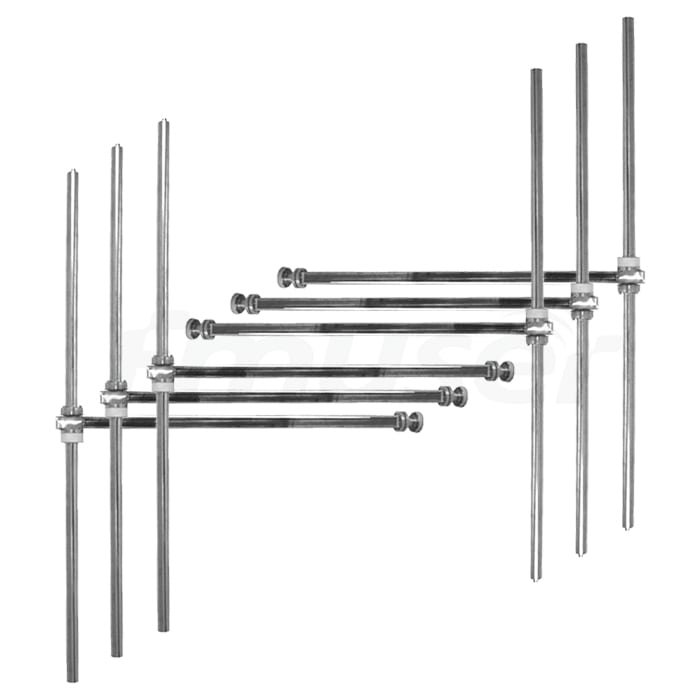
A log periodic dipole array (LPDA) is a directional antenna that consists of multiple dipole elements arranged in a way that provides a wide frequency range response. The antenna is designed to provide good performance across a broad frequency spectrum, which makes it ideal for use in situations where multiple frequencies are used. LPDAs are often used in broadcasting as well as for amateur radio applications.
FM log periodic dipole arrays are a type of directional FM antenna that uses a series of parallel dipoles arranged in a specific sequence to create a broad bandwidth. They are capable of providing high gain and directional coverage, but are more complex to design and install than other types of FM antennas. They are typically used in single bay configurations and require specialized equipment for installation and mounting.Terms Specifications Advantages Broad frequency range, directional Disadvantages Directional, requires precise aiming Equipment Needed Coaxial cable, mounting bracket, RF amplifier Bay Configuration Multi-bay Coax Connector type Type N or 7/16 DIN Frequency Range 85-170 MHz Power-Handling Capacity Up to 1 kW Directionality Directional Antenna Gain 8-10 dBi Price $1,000-$3,000 Structure Arrays of dipoles Installation Height 20-30 feet above ground level Applications Broadcast radio, amateur radio Installation Requirements Must be precisely aimed, requires a clear line of sight to the transmitterMaintenance Periodic cleaning and inspection FM Discone Antenna
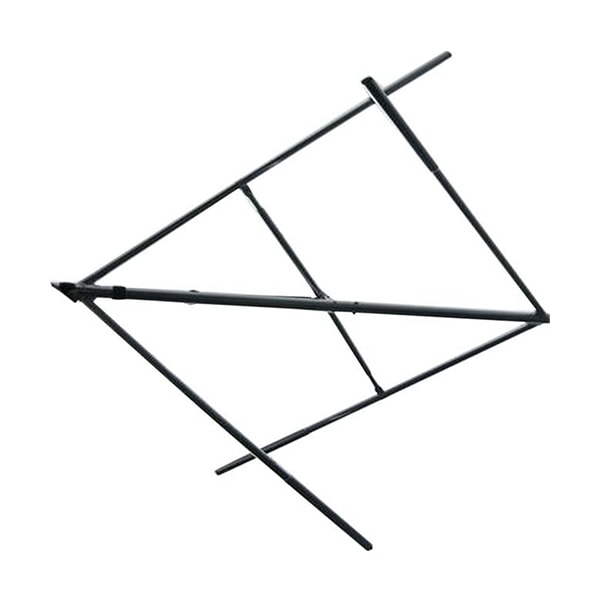
FM Discone antennas are a type of broadband antenna that can be used for FM radio broadcasting and reception. They work by combining a vertically polarized dipole with disc-shaped elements to create a broad frequency response. Advantages of Discone antennas include their wide bandwidth and omnidirectional coverage. Disadvantages include their limited gain and susceptibility to environmental interference. They are typically used in single bay configurations and connected via a BNC or N-type coax connector.
FM Helical Antenna
FM Helical antennas are a type of compact cylindrical antenna used for FM broadcasting and reception. They work by transmitting and receiving signals through a helical coil that is tuned to a specific frequency range. Advantages of helical antennas include their compact size, directional coverage, and ability to provide high gain. Disadvantages include their limited bandwidth and susceptibility to interference. They are typically used in single bay configurations and connected via a BNC or SMA coax connector.
A helical antenna is a type of directional antenna that is shaped like a helix. The antenna uses a helical conductor to create a circularly polarized signal, which makes it ideal for use in situations where radio signals need to be transmitted over long distances. Helical antennas are often used in radio communication systems.Terms Specifications Advantages Directional, circularly polarized Disadvantages Lower gain, larger size Equipment Needed Coaxial cable, mounting bracket, RF amplifier Bay Configuration Single bay only Coax Connector type Type N or 7/16 DIN Frequency Range 100-900 MHz Power-Handling Capacity Up to 1 kW Directionality Directional Antenna Gain 5-8 dBi Price $100-$500 Structure Helically wound wire Installation Height 15-25 feet above ground level Applications Radio communication systems Installation Requirements Must be precisely aimed, requires a clear line of sight to the transmitterMaintenance Periodic cleaning and inspection FM radio antenna for car with suction pad
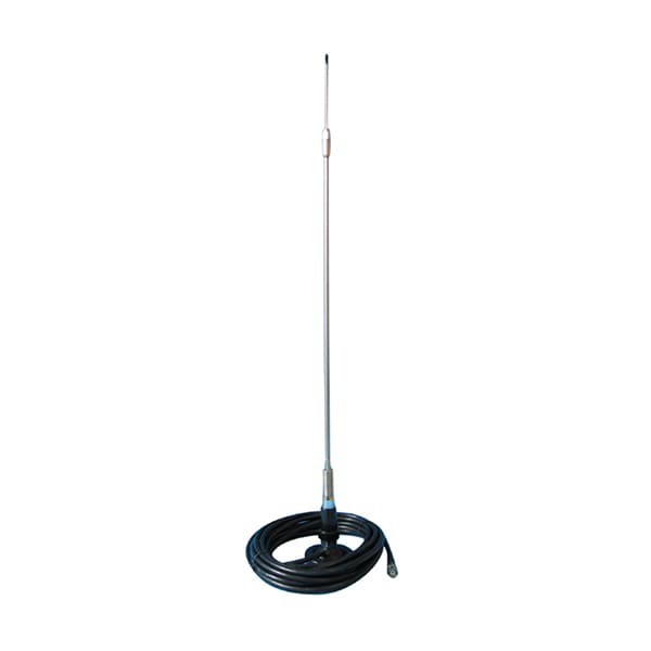
FM radio antennas for cars are typically small, portable antennas that attach to the car's windshield or other surfaces using a suction cup. They work by receiving radio signals and transmitting them to the car's radio receiver. Advantages of portable car antennas include their ease of use and low cost. Disadvantages include their lower gain and susceptibility to interference. They are typically connected via a coax cable with a standard car radio connector.
An FM radio antenna for a car is a small, omnidirectional antenna that is designed to be mounted on a car’s windshield using a suction pad. The antenna is generally used to improve the reception of FM radio stations while driving.Terms Specifications Advantages Portable, easy to install, low cost Disadvantages Lower gain, limited frequency range Equipment Needed None Bay Configuration Single bay only Coax Connector type F-type connector Frequency Range 88-108 MHz Power-Handling Capacity Up to 50 W Directionality Omnidirectional Antenna Gain 1-2 dBi Price $10-$50 Structure Small whip antenna with a suction pad for mounting Installation Height Mounted on car windshield Applications Improved FM radio reception while driving Installation Requirements None Maintenance Periodic cleaning and inspection FM dipole antenna
FM dipole antennas are a type of omnidirectional FM antenna that uses two parallel rods or wires to receive or transmit signals in equal fashion for this type. Dipole antennas are simple and low-cost, though their gain can be limited. They are connected via a coaxial cable with a standard 75 Ohm connector.
An FM dipole antenna is a popular antenna used for FM radio reception. The antenna consists of two conductors, each one-quarter wavelength long, oriented perpendicular to each other. This provides good omnidirectional coverage, and the antenna is insensitive to the polarity of the incoming signal.Terms Specifications Advantages Good omnidirectional coverage, easy to install, low costDisadvantages Lower gain than directional antennas Equipment Needed Coaxial cable, mounting bracket Bay Configuration Single bay only Coax Connector type F-type connector Frequency Range 88-108 MHz Power-Handling Capacity Up to 50 W Directionality Omnidirectional Antenna Gain 2-4 dBi Price $10-$50 Structure Two metal rods or wires oriented perpendicular to each otherInstallation Height 10-20 feet above ground level Applications FM radio reception for homes, offices, and vehicles Installation Requirements None Maintenance Periodic cleaning and inspection FM circularly polarized antenna
FM circularly polarized antennas are a type of antenna used for specialized applications such as satellite communication. They work by producing a circularly polarized radiation pattern, which allows for better signal reception and transmission in certain situations. Advantages of circularly polarized antennas include their ability to minimize interference, better signal quality, and increased range. Disadvantages include their higher cost and more complex installation. They are typically used in single bay configurations and connected via an N-type coax connector.
A circularly polarized antenna is a type of antenna that emits signals in a circular pattern, as opposed to the linear pattern of a dipole antenna. This type of antenna is often used in situations where there are obstructions, as the circular pattern allows for better signal penetration. Circularly polarized antennas are often used in satellite communication systems.Terms Specifications Advantages Good signal penetration, flexible frequency range Disadvantages More complex design, higher cost Equipment Needed Coaxial cable, mounting bracket, RF amplifier Bay Configuration Multi-bay Coax Connector type Type N or 7/16 DIN Frequency Range 87.5-108 MHz Power-Handling Capacity Up to 5 kW Directionality Directional or omnidirectional Antenna Gain 4-12 dBi Price $500-$2,000 Structure Cone-shaped with multiple circular elements Installation Height 30-50 feet above ground level Applications Satellite communication, broadcast radio Installation Requirements Must be precisely aimed, requires a clear line of sight to the transmitterMaintenance Periodic cleaning and inspection FM yagi antenna
FM yagi antennas are a type of directional antenna used for FM radio broadcasting and reception. They work by using a series of passive elements arranged in specific configurations to create directional coverage and high gain. Advantages of yagi antennas include their high gain, directional coverage, and ability to minimize interference. Disadvantages include their complex design and mounting requirements. They are typically used in single bay configurations and connected via an N-type coax connector.
A yagi antenna is a directional antenna with a series of elements mounted on a metal boom. It has high gain and directional sensitivity, making it popular for a variety of applications. Yagi antennas are used in radio and television broadcasting, as well as in amateur radio applications.Terms Specifications Advantages High gain, directional sensitivity Disadvantages Must be precisely aimed, limited frequency range Equipment Needed Coaxial cable, mounting bracket, RF amplifier Bay Configuration Single or multi-bay Coax Connector type Type N or 7/16 DIN Frequency Range 88-108 MHz Power-Handling Capacity Up to 5 kW Directionality Directional Antenna Gain 10-15 dBi Price $100-$500 Structure Metal boom with a series of elements Installation Height 20-50 feet above ground level Applications Broadcast radio, amateur radio, television broadcastingInstallation Requirements Must be precisely aimed, requires a clear line of sight to the transmitterMaintenance Periodic cleaning and inspection FM ground plane antenna
FM ground plane antennas are a type of antenna used for FM radio broadcasting and reception. They work by providing a ground plane and a vertical radiator that serves as the antenna element. Advantages of ground plane antennas include their omnidirectional coverage and ease of installation.
Ground plane antennas can be single bay or multi-bay. Single bay antennas are generally more compact and easier to install, while multi-bay antennas provide greater coverage and higher gain. They can be connected via an N-type coax connector and typically have a frequency range of 88-108 MHz.
In terms of power handling capacity, which refers to the maximum amount of power that the antenna can handle without damage, it will depend on the specific model and manufacturer. Directionality of FM ground plane antennas is typically omni-directional, meaning they can receive and transmit signals in all directions.
Antenna gain, which refers to the amount of amplification provided by the antenna, varies depending on the design and size of the antenna. Ground plane antennas typically have lower gain than directional antennas such as yagi antennas.
Prices for FM ground plane antennas can range from $50-$200 for single bay models and $1000 or more for multi-bay models. In terms of structure, FM ground plane antennas typically consist of a vertical radiator and a ground plane of several radials extending outward, forming an umbrella shape.
Installation height and performance will depend on the specific application and environment in which the antenna is used. Generally, FM ground plane antennas should be installed as high as possible to ensure optimal coverage and signal quality.
Ground plane antennas can be used for a variety of applications, including broadcasting, public safety, and commercial communication systems. Installation requirements will vary depending on the specific antenna, but in general, they are relatively easy to install.
Maintenance and repair requirements will depend on the specific model and manufacturer. In some cases, periodic cleaning or inspection may be required to ensure proper function. In the event of damage, repairs or replacement of damaged components may be necessary.
- How to differ directional and omni-directional FM broadcast antenna?
- Directional FM broadcast antennas and omni-directional FM broadcast antennas have several differences, including the following:
1. Directionality: The primary difference between the two types of antennas is their directionality. Omni-directional antennas radiate their signal equally in all directions, while directional antennas focus their signal more in one or more specific directions.
2. Related equipment: Directional antennas require additional equipment to control the directionality of the signal, such as mechanical or electrical systems that can adjust the antenna's orientation. Omni-directional antennas generally do not require this additional equipment.
3. Advantages: Directional antennas can be useful for broadcasting to specific areas or to avoid interference from other signals. They can also be more efficient in terms of signal strength and range in certain directions. Omni-directional antennas are simpler to install and maintain and are ideal for broadcasting to large geographic areas.
4. Disadvantages: Directional antennas are typically more complex and expensive to install and maintain than omni-directional antennas. They also require careful planning and alignment to ensure that the directional focus is properly directed. Omni-directional antennas may have a more limited range and may be more susceptible to interference.
5. Prices: The price of the antennas varies depending on the type, manufacturer, and features. Generally, directional antennas tend to be more expensive than omni-directional antennas due to the additional equipment required for directionality control.
6. Applications: Directional antennas may be used in situations where it is important to avoid interference from other signals or to target specific areas, such as in urban or mountainous areas. Omni-directional antennas are often used in rural areas where there are fewer competing signals.
7. Performance: Directional antennas can provide higher signal strength and range in certain directions, while omni-directional antennas provide more consistent coverage over a larger geographic area.
8. Structures: The structures of directional and omni-directional antennas are similar, but directional antennas may be larger or more complex due to the additional equipment required for directionality control.
9. Frequency: Both types of antennas can be used for various FM frequencies.
10. Installation, repairment, and maintenance: The installation process and maintenance requirements for directional and omni-directional antennas are similar, but directional antennas may require more specialized expertise for proper installation and maintenance due to their complexity.
Overall, the choice between directional and omni-directional FM broadcast antennas will depend on the specific needs and circumstances of the broadcaster. While directional antennas can offer advantages in certain situations, they are generally more complex and expensive to install and maintain. Omni-directional antennas are simpler and more cost-effective, but may have some limitations in terms of signal strength, range, and interference.
- How to increase the broadcast coverage of an FM broadcast antenna?
- There are several methods that can be used to increase the broadcast coverage of an FM broadcast antenna, including the following:
1. Increase antenna height: The higher the antenna is located, the greater the broadcast coverage area will be. This is due to the reduced impact of physical obstacles such as buildings and trees, as well as the curvature of the earth.
2. Improve antenna design: The design of the antenna can play a significant role in the coverage area. Optimizing the antenna design for the specific frequency, terrain, and other environmental factors can increase the efficiency and range of the signal.
3. Use a directional antenna: A directional antenna can be oriented towards the target coverage area, which can help to optimize the signal strength in that direction.
4. Increase transmitter power: Increasing the power of the transmitter can also increase the range of the broadcast signal, although this may have limitations due to regulatory restrictions and physical limitations.
5. Use a higher-quality feedline: Using high-quality feedline can improve the efficiency of the transmission, which can translate into better coverage.
6. Reduce interference: Reducing interference from other signals can allow the broadcast signal to be received more clearly and over a larger area.
7. Use multiple antennas: Using multiple antennas can help to cover larger or more complex areas. This can be accomplished through a variety of techniques, such as using multiple dipole antennas in an array or using a combination of omni-directional and directional antennas.
Overall, the most effective way to increase the broadcast coverage of an FM broadcast antenna will depend on the specific circumstances and limitations of the broadcasting environment. Working with a professional antenna design and installation company can help to identify the most effective strategies for optimizing coverage area and achieving the desired broadcasting goals.
- What are the most important specifications of an FM broadcast antenna?
- The most important physical and RF specifications of an FM broadcast antenna include the following:
1. Frequency range: The frequency range specifies the range of frequencies that the antenna is capable of transmitting and receiving, typically measured in megahertz (MHz).
2. Power handling capacity: The power handling capacity specifies the maximum power that the antenna can handle without sustaining damage, usually measured in watts.
3. Gain: The gain of the antenna is a measure of how efficiently it radiates electromagnetic energy. It is typically measured in decibels (dB), and higher gain antennas can provide greater signal strength and range.
4. Polarization: The polarization of the antenna refers to the orientation of the electromagnetic field of the signal. FM broadcast antennas typically use vertical polarization, although other types of polarization may be used in certain circumstances.
5. Radiation pattern: The radiation pattern of the antenna describes how the electromagnetic energy is distributed in space around the antenna. This can be influenced by the design of the antenna and can impact the coverage area and interference levels.
6. Impedance: The impedance of the antenna refers to the overall resistance to an AC current that the antenna presents to the transmitted signal. It is typically measured in ohms and must match the impedance of the transmitter and transmission line for efficient transmission.
7. Resonance: The resonance of the antenna refers to the ability of the antenna to efficiently transmit a specific frequency. A resonant antenna will have the greatest efficiency and signal strength at its resonant frequency.
8. VSWR: VSWR (Voltage Standing Wave Ratio) is a measure of how efficiently the antenna is connected to the transmission line. High VSWR can result in power loss and potential damage to the transmitter or antenna.
Overall, these RF and physical specifications are critical to ensure that the FM broadcast antenna is capable of efficiently transmitting the desired signal strength and coverage area, while also protecting the equipment and complying with regulatory requirements.
- What are the common cabling components for FM broadcast antenna installation?
- The common cabling components for FM broadcast antenna installation include:
1. Coaxial Cable - This type of cable is used to transmit the audio and RF signals from the transmitter to the antenna. The most commonly used type for FM broadcast is 7/8" Heliax cable.
2. Connectors - These are used to connect the coaxial cable to other equipment such as the transmitter, the antenna, or a lightning arrestor. Common types of connectors used in FM broadcast antenna installations include Type-N, BNC, and 7/16 DIN.
3. Lightning Arrestor - This is a device that is used to protect the transmitter and other equipment from damage due to lightning strikes. It is typically installed between the antenna and the transmitter.
4. Grounding Kit - This is used to ground the coaxial cable and the antenna. It is important to ground the antenna and the coaxial cable to prevent build-up of static electricity and to protect from damage due to a lightning strike.
5. Tower Sections - These are used to support the antenna and other equipment. They are typically made of steel or aluminum and come in various lengths.
6. Antenna Mount - This is used to mount the antenna to the tower sections. It can either be a fixed mount or a rotatable mount, depending on the type of antenna being used.
7. Guy Wires - These are used to provide additional stability to the tower sections and the antenna. They are typically made of steel and anchored to the ground.
8. Tower Hardware - This includes bolts, nuts, washers, and other hardware used to secure the tower sections and equipment to the tower.
9. Cable Ties - These are used to secure the coaxial cable to the tower sections, cable trays, or other supporting structures.
Overall, the cabling components for FM broadcast antenna installation are critical for ensuring a quality and reliable broadcast. Proper installation, grounding, and maintenance of these components is essential for achieving optimal performance and protecting the equipment from damage.
- What are common materials used to make an FM broadcast antenna?
- There are various materials used in the manufacture of FM broadcast antennas. Some of the most common materials include:
1. Aluminum: Aluminum is commonly used in the construction of FM broadcast antennas due to its lightweight and durable properties. It can be easily shaped and formed into various antenna designs.
2. Stainless steel: Stainless steel is another common material used in FM broadcast antennas due to its high strength and resistance to corrosion. It can withstand exposure to harsh environmental conditions, maintaining the integrity and performance of the antenna over time.
3. Fiberglass: Fiberglass is often used as an insulating material in FM broadcast antennas. It can also provide structural support to the antenna and is resistant to corrosion.
4. Copper: Copper is used in the construction of antenna coils, as it is a highly conductive material. It can be used for inductors, transformers, and other antenna components.
5. Dielectric materials: Dielectric materials, such as plastic, polymer, and ceramics, are used to insulate or separate certain components of the antenna. They can also be used as a substrate for printed circuit antennas.
Overall, the choice of materials used in the FM broadcast antenna will depend on various factors, such as the specific application, frequency range, strength requirements, and environmental conditions. Working with a professional antenna design and installation company can help to identify the most suitable materials for the antenna to ensure optimal performance and durability.
- Are there any important terminologies of FM broadcast antenna?
- Sure, here are some commonly used terminologies related to FM broadcast antennas and what they mean:
1. Frequency range: The frequency range is a measure of the range of frequencies at which the FM broadcast antenna can operate efficiently. The FM broadcast frequency range is 87.5 MHz to 108 MHz.
2. Antenna gain: Antenna gain is a measure of the power of an antenna relative to a reference antenna. In the context of FM broadcast antennas, it refers to how well the antenna radiates electromagnetic energy. The higher the gain, the more effective the antenna is at transmitting and receiving FM signals.
3. Polarization: Polarization is the orientation of the antenna's electromagnetic field. In FM broadcasting, vertical polarization is the most common, and it refers to the direction of the radio wave that is perpendicular to the earth's surface.
4. Radiation pattern: Radiation pattern refers to the spatial distribution of the electromagnetic energy produced by the antenna. It is influenced by the antenna design and can shape how the FM signal is broadcast in specific directions.
5. Impedance: Impedance refers to the level of resistance to an AC current that the antenna presents to the FM signal. It is measured in ohms and is essential to ensure the efficient transmission of the FM signal.
6. Standing wave ratio (SWR): Standing wave ratio, or SWR, is a measure of the efficiency of the antenna system. It indicates the degree to which the antenna system has mismatched impedance, with a low SWR indicating more efficient transmission.
7. Resonance: Resonance refers to the natural frequency at which the antenna system efficiently transmits the FM signal. This is important for maximizing efficiency and improving the range of the antenna.
8. VSWR: VSWR stands for Voltage Standing Wave Ratio, and it measures the radio frequency energy reflected back towards the transmitter. Higher VSWR can cause signal loss and potential damage to the transmitter or antenna.
9. Beamwidth: Beamwidth is the angle between the two points on the radiation pattern where the power has decreased to half of the maximum value. It describes the coverage area and directivity of the antenna and is an important consideration for designing and positioning the antenna.
10. Front-to-back ratio: Front-to-back ratio is a measure of the level of radiation intensity in the forward direction compared to the radiation intensity in the opposite direction from the antenna. It is important for ensuring that the antenna effectively transmits the FM signal and does not interfere with other signals.
11. Side lobe suppression: Side lobe suppression refers to the ability of the antenna to reduce the level of radiation in directions other than the desired main lobe direction. This is important for reducing interference with neighboring signals and improving the signal to noise ratio.
12. Bandwidth: Bandwidth is the range of frequencies that the antenna can effectively transmit and receive. It is typically expressed as a percentage of the center frequency and is important for ensuring that the FM signal is transmitted within the range of specified frequencies.
13. Power handling capacity: Power handling capacity is the maximum amount of power that the antenna can handle without sustaining damage. This is an important consideration for ensuring the proper function and safety of the FM broadcast system.
14. Lightning protection: Lightning protection is an essential part of FM broadcast antenna systems to protect against damage from lightning strikes. It typically involves the installation of lightning arrestors, grounding equipment, and surge suppressors.
Understanding these terminologies is important for designing, selecting, and optimizing an FM broadcast antenna system to ensure the efficient transmission of the FM signal and meeting regulatory requirements. Working with a professional antenna design and installation company can help to ensure that the antenna system meets all necessary specifications and delivers optimal performance.
- How to differ commercial and consumer-level FM broadcast antenna?
- There are several differences between a commercial FM broadcast antenna and a consumer-level FM broadcast antenna. Here are some of the major differences:
1. Equipment used and structure: Commercial FM broadcast antennas are typically larger and more complex than consumer-level FM broadcast antennas. They require specialized equipment, such as high-power transmitters and tower-mounted amplifiers, and are often designed for specific applications and coverage areas. Consumer-level FM broadcast antennas are often smaller and less complex, designed for indoor or outdoor use and typically do not require specialized equipment.
2. Frequency range: Commercial FM broadcast antennas operate within a wider frequency range than consumer-level FM broadcast antennas. This is because commercial FM broadcasts may have various channels within the same coverage, providing regional coverage areas. For instance, a commercial FM station may have multiple channels with specific coverage areas, such as a city or region.
3. Applications: Commercial FM broadcast antennas are typically used for large-scale radio broadcasting applications, such as broadcasting on a regional or national level. Consumer-level FM broadcast antennas are typically used for more localized broadcasting, such as for home or car audio.
4. Performance: Commercial FM broadcast antennas may offer higher performance and greater coverage area than consumer-level FM broadcast antennas, due to their larger size and greater complexity. They may be designed with multiple elements and directional features, allowing for enhanced signal strength and clarity.
5. Installation and maintenance: Commercial FM broadcast antennas often require professional installation and maintenance, due to their complexity and specialized equipment. Consumer-level FM broadcast antennas can often be easily installed by the end-user, and may only require minor maintenance or adjustments.
6. Price: Commercial FM broadcast antennas are typically much more expensive than consumer-level FM broadcast antennas. This is due to their larger size, specialized equipment requirements, and greater complexity.
In summary, the main differences between commercial FM broadcast antennas and consumer-level FM broadcast antennas are related to their size, equipment requirements, frequency range, performance, applications, installation, maintenance, and price. Choosing the appropriate antenna will depend on the specific needs of the broadcast application, budget, and other factors.
- How to choose FM broadcast antenna base on FM transmitter power output level?
- There are various types of FM broadcast antennas available, and they can be categorized based on several factors, including power-level, transmitter size, and mounting type. Here are some of the most common types of FM broadcast antennas:
1. Low Power FM antennas: These antennas are typically used for low power FM transmitters, which have a power output of less than 1000 watts. These antennas are usually smaller in size and can be mounted on a roof or a tripod.
2. Medium Power FM antennas: These antennas are designed for FM transmitters with a power output between 1000 watts and 10,000 watts. They are typically larger in size and can be mounted on a tower or a mast.
3. High Power FM antennas: These antennas are designed for high power FM transmitters, with a power output of 10,000 watts or more. They are the largest and most complex type of FM broadcast antennas and are typically mounted on tall structures such as towers or guyed masts.
4. Rack-type FM transmitter antennas: Rack-type FM transmitters are designed to be mounted in a standard 19-inch equipment rack. These transmitters are typically lower power than stand-alone transmitters and can use various types of FM antennas, such as dipole or collinear antennas.
5. Solid-state cabinet FM transmitter antennas: Solid-state cabinet FM transmitters typically use collinear or panel antennas and can be used for medium to high power applications. These transmitters may have multiple amplifier modules, and the antenna configuration can be adjusted to accommodate various coverage areas.
6. Single bay FM antennas: These antennas consist of a single antenna bay, or element, and are typically used for lower power FM transmitters. They may be omnidirectional or directional, with the radiation pattern depending on the design.
7. Multi-bay FM antennas: Multi-bay antennas consist of multiple antenna bays or elements and are used for higher power applications. They can be designed as directional or omnidirectional antennas, depending on the desired coverage area.
Some of the key factors that differentiate these types of FM antennas include their size, power handling capabilities, radiation pattern, frequency response, and construction materials. There is no one-size-fits-all solution, and choosing the proper FM antenna will depend on a variety of factors, including the broadcasting coverage area, transmitter power requirements, budget, and other factors.
It is important to consult with a professional antenna designer and installer to ensure that the appropriate FM antenna is selected for the specific application and to ensure optimal performance.
- How many types of FM broadcast antenna are there?
- There are various types of FM broadcast antennas available, and they can be categorized based on several factors, including power-level, transmitter size, and mounting type. Here are some of the most common types of FM broadcast antennas:
1. Low Power FM antennas: These antennas are typically used for low power FM transmitters, which have a power output of less than 1000 watts. These antennas are usually smaller in size and can be mounted on a roof or a tripod.
2. Medium Power FM antennas: These antennas are designed for FM transmitters with a power output between 1000 watts and 10,000 watts. They are typically larger in size and can be mounted on a tower or a mast.
3. High Power FM antennas: These antennas are designed for high power FM transmitters, with a power output of 10,000 watts or more. They are the largest and most complex type of FM broadcast antennas and are typically mounted on tall structures such as towers or guyed masts.
4. Rack-type FM transmitter antennas: Rack-type FM transmitters are designed to be mounted in a standard 19-inch equipment rack. These transmitters are typically lower power than stand-alone transmitters and can use various types of FM antennas, such as dipole or collinear antennas.
5. Solid-state cabinet FM transmitter antennas: Solid-state cabinet FM transmitters typically use collinear or panel antennas and can be used for medium to high power applications. These transmitters may have multiple amplifier modules, and the antenna configuration can be adjusted to accommodate various coverage areas.
6. Single bay FM antennas: These antennas consist of a single antenna bay, or element, and are typically used for lower power FM transmitters. They may be omnidirectional or directional, with the radiation pattern depending on the design.
7. Multi-bay FM antennas: Multi-bay antennas consist of multiple antenna bays or elements and are used for higher power applications. They can be designed as directional or omnidirectional antennas, depending on the desired coverage area.
Some of the key factors that differentiate these types of FM antennas include their size, power handling capabilities, radiation pattern, frequency response, and construction materials. There is no one-size-fits-all solution, and choosing the proper FM antenna will depend on a variety of factors, including the broadcasting coverage area, transmitter power requirements, budget, and other factors.
It is important to consult with a professional antenna designer and installer to ensure that the appropriate FM antenna is selected for the specific application and to ensure optimal performance.
- Does FM broadcast antenna equals to FM transmitter antenna or FM radio antenna, why?
- An FM broadcast antenna is not the same as an FM transmitter antenna or an FM radio antenna, although they are all related to broadcasting or receiving FM radio signals.
An FM broadcast antenna is designed specifically for transmitting an FM radio signal from a radio station to the listeners within the coverage area. The antenna is typically mounted on a tower or mast and is connected to a high-power FM transmitter that broadcasts the radio signal.
An FM transmitter antenna, on the other hand, is the radiator element of an FM transmitter system that converts the electrical signal from the transmitter into an electromagnetic signal that can be received by an FM radio.
An FM radio antenna is a component of an FM radio that is designed to receive radio signals transmitted by FM broadcast antennas and FM transmitter antennas. This antenna can be a built-in or an external component of the FM radio and is typically designed to be omnidirectional or directional, depending on the location and the desired signal quality.
While these antennas have different purposes, they all play a crucial role in the FM broadcasting and receiving process. The FM broadcast antenna transmits the FM radio signal, the FM transmitter antenna converts the electrical signal into an electromagnetic signal, and the FM radio antenna receives the FM radio signal for playback.
- What are the differences between high power and low power FM broadcast antenna?
- The differences between FM broadcast antennas for FM transmitters with different power levels can vary significantly, including their configuration, price, bays numbers of the antenna, performance, size, installation, vulnerability, repairment, and maintenance requirements. Here are some of the key differences:
1. Configuration: Low-power FM antennas are typically smaller and more straightforward, with fewer features than larger, higher-power FM antennas. Higher power FM antennas are more complex, with more elements and a greater degree of directionality to focus the broadcast signal in specific coverage areas. Multi-bay antennas can vary in configuration, depending on the design requirements and the amount of gain and directionality required.
2. Price: The price of an FM broadcast antenna can vary significantly based on its size and complexity. Higher power FM broadcast antennas tend to have a higher price point than lower-power antennas, due to their size and complexity.
3. Number of bays: FM broadcast antennas can have a varying number of bays based on the application and power output of the FM transmitter. Higher power FM broadcast antennas typically have a greater number of bays, with multi-bay antennas being the most complex and featuring dozens of bays.
4. Performance: The performance of FM broadcast antennas can vary widely, depending on their size, configuration, and other factors. Higher power FM broadcast antennas tend to offer greater directionality and gain, allowing for better signal transmission over longer distances.
5. Size: FM broadcast antennas for lower-power transmitters are typically smaller and more lightweight, while higher power FM antennas can be much larger and heavier. Multi-bay antennas can be particularly large and require a sturdy support structure.
6. Installation: Installing an FM broadcast antenna requires professional expertise, regardless of the power output of the associated FM transmitter. Higher power FM antennas require more complex installations, as they may be tower-mounted and require more extensive structural support.
7. Vulnerability: Higher power FM broadcast antennas can be more vulnerable to damage due to their size and complex configuration. Inclement weather and other environmental factors can impact their performance.
8. Repair and maintenance: FM broadcast antennas require regular maintenance to ensure optimal performance. Repairs may be more complex for larger, higher-power FM broadcast antennas.
Overall, the primary differences between FM broadcast antennas for FM transmitters with different power levels relate to their size, complexity, and associated costs. Higher power FM broadcast antennas are typically more complex and require more extensive installations, but can also offer greater performance capabilities. Choosing the appropriate FM broadcast antenna will depend on a variety of factors, including the broadcasting coverage area, transmitter power requirements, budget, and other factors.
- How to test FM broadcast transmitter with an FM broadcast antenna?
- Before testing your FM transmitter, you should use an FM broadcast antenna and not a dummy load. This is because dummy loads are designed for testing at low power levels and can only handle a limited amount of power. Using a dummy load with an FM transmitter operating at higher power levels could cause damage to the load or the transmitter itself.
To properly test an FM broadcast transmitter, follow these steps:
1. Set up the FM broadcast antenna in a location that allows for optimal signal transmission and reception. This could be on a tower or mast, or indoors with an antenna suitable for the transmitter’s frequency and power.
2. Connect the FM transmitter to the antenna using appropriate coaxial cables that match the impedance of the transmitter and antenna.
3. Power on the FM transmitter and adjust the output power level to the desired setting, being careful not to exceed the maximum output power rating of the transmitter.
4. Check the transmitter for any warnings or error messages, and ensure that all settings are configured correctly.
5. Use an FM radio receiver to test the transmitter signal by tuning to the broadcast frequency and checking for a clear, strong signal. If necessary, adjust the transmitter and antenna configuration to optimize performance.
6. Monitor the transmitter and antenna for any signs of damage or overheating, and ensure that they are properly grounded to prevent electrical interference or other issues.
By using an FM broadcast antenna, taking care not to exceed the transmitter’s maximum power output, and monitoring the system for proper operation and performance, you can properly test an FM broadcast transmitter. It is important to follow all safety guidelines and best practices to prevent damage to equipment and ensure optimal signal quality.
- What situation may fails an FM broadcast antenna from working?
- There are several factors that could potentially cause an FM broadcast antenna to stop working properly or fail altogether. Some of these situations, reasons, or inappropriate manual operating methods could include:
1. Damage to the antenna due to inclement weather, such as high winds, lightning, and ice.
2. Improper installation or maintenance of the antenna, including failure to ground the antenna properly or secure it to the tower or mast.
3. Environmental or human factors affecting antenna performance, including electromagnetic interference from nearby equipment, interference from other broadcast signals, or nearby construction or building activities.
4. Inadequate maintenance or repair of the antenna, including failure to replace damaged components or inspect the antenna regularly.
As an FM radio station technician, it is essential to avoid these situations by adhering to best practices for installation, maintenance, and repair of FM broadcast antennas. Here are some key steps to follow:
1. Properly install the antenna by mounting it on a secure tower or mast and grounding it correctly.
2. Regularly inspect the antenna structure for damage or wear and replace any damaged components or connectors as needed.
3. Test the antenna periodically to ensure proper signal transmission and reception, and adjust the configuration as needed to optimize performance.
4. Maintain a clear area around the antenna to avoid any interference from nearby activities or buildings, and be careful to avoid electromagnetic interference from other equipment.
5. For higher-power FM radio stations, adhere to all relevant guidelines and regulations governing antenna installation and operation, and obtain any necessary permits or certifications required by local or national governments.
By following these guidelines and keeping up with regular maintenance and inspections, you can ensure that the FM broadcast antenna operates properly and avoids potential factors that could cause it to fail or stop working correctly.
- How to correctly maintain an FM broadcast antenna?
- To correctly use and maintain an FM broadcast antenna, and increase its life-expectancy, consider the following guidelines:
1. Proper installation: Ensure that the antenna is installed according to the manufacturer's instructions and industry standards. This includes mounting the antenna on a sturdy tower or mast, carefully aligning it to the desired coverage area, and properly grounding the antenna to prevent electrical interference.
2. Regular inspections: Regularly inspect the antenna structure for signs of damage or wear, including worn out mast, rusted elements, damaged coaxial cables or connectors. Perform a structural and electrical inspection yearly, to identify damaged components and faults in the system. Also, make sure that the antenna is free from any debris or vegetation that can cause signal degradation and potential damage to the structure.
3. Maintenance: Perform routine maintenance on the antenna, including cleaning, replacement of damaged components, and tightening connections at regular intervals. Check cables for signs of wear and damage, as well as ground connections and lightning protection.
4. Testing: Conduct periodic testing of the antenna system to ensure optimal performance, especially when any changes to the installation, transmitter output, frequency, location, or weather condition occur. Proper testing will ensure that the output power and VSWR of the transmitter match the antenna system providing the best possible signal quality for the broadcast.
5. Safety precautions: Take necessary safety precautions when working on the FM broadcast antenna, such as using safety harnesses or personnel lifts when accessing high parts of the antenna system.
6. Repair: Promptly address any issues that arise, such as damaged parts and connections, or if there are any performance issues affecting the broadcast. Conduct a thorough inspection and replacement of faulty components promptly.
By following these guidelines, you can extend the lifespan of the FM broadcast antenna, minimize downtime and equipment failures, and ensure optimal performance of the FM broadcasting signal coverage in your station.
- How to repair an FM broadcast antenna if it fails working?
- If an FM broadcast antenna fails to work, the first step is to identify the root cause of the problem. This may require a thorough inspection of the antenna structure and components, as well as testing the transmitter and other system components to determine where the issue is originating from.
Here are some steps to repair an FM broadcast antenna:
1. Assess the problem: Figure out the root cause of the antenna failure. Determine whether the failure is related to the antenna itself, the transmission line, the transmitter, or other related equipment.
2. Fix the immediate issue: If the issue is related to a specific component, such as a damaged connection or a broken element, replace or repair the component as soon as possible to prevent further damage to the system.
3. Test the repairs: Once repairs have been made, test the system to ensure that it is performing optimally. This may involve checking transmission power and antenna signal strength, as well as conducting dummy load tests.
4. Document repairs: Keep a detailed record of any repairs that are made to the FM broadcast antenna, including what was repaired or replaced, when it was done, and who performed the repairs. This information will be valuable in future maintenance and troubleshooting tasks.
5. Prevent future issues: Take preventative measures to avoid potential equipment failures in the future, including conducting regular maintenance, inspections, and testing of the system. These steps will identify issues early, so they can be remedied before they lead to more severe equipment failure.
It's essential to note that repairing an FM broadcast antenna involves a high risk of working at heights, electrical hazards, and the use of specialized equipment. It is recommended to work with a team of trained and experienced professionals who can address the repair needs and ensure that the system is functioning correctly.
- Can I use brand A's FM broadcast antenna along with brand B's FM transmitter?
- Yes, it is generally possible to use an FM broadcast antenna manufactured by one brand with an FM transmitter manufactured by another brand to broadcast audio programs. However, there are some important considerations to keep in mind in order to ensure that the two systems will work together properly.
Here are some factors to consider:
1. Frequency compatibility: Make sure that the frequency range of the FM broadcast antenna is compatible with the FM transmitter. This will depend on the specific frequency range allocated for FM broadcasts in your country and region, as they may vary.
2. Power levels: Ensure that the FM broadcast antenna and FM transmitter’s power ratings match. Using a mismatched equipment can result in poor signal quality, frequency drift, improper SWR and even damage to the system.
3. Impedance Matching: Verify the impedances of the antenna and the transmitter to ensure they are matched. This helps minimize signal loss and ensure proper SWR of the transmission system.
4. Cable compatibility: Ensure that the cables used to connect the FM transmitter and antenna are compatible and have the correct connector type for both devices.
5. Interference: The use of different brands of equipment may or may not cause interference problems that can affect signal transmission. If there are interferences while using the combined system, it may be caused by electromagnetic compatibility issues and shielded cables and filters to minimize interference may be recommended.
In general, it is important to ensure that the FM broadcast antenna and FM transmitter are compatible and work optimally together. It may be possible to obtain technical support from the manufacturers to confirm compatibility and optimal usage guides.
- How to recognize if an FM broadcast antenna is of high quality?
- There are several factors to consider when assessing the quality of an FM broadcast antenna, including:
1. Frequency range: A high-quality FM broadcast antenna should be designed to operate across the entire FM broadcast band's frequency range. It should be able to handle maximum allowed transmitter output power and have low VSWR.
2. Gain: A high-quality FM broadcast antenna should also have a high gain, which measures the antenna's ability to amplify the signal it receives. The higher the gain, the better the performance.
3. Beamwidth: The beamwidth of the FM broadcast antenna should be narrow and focused to direct the signal where it's needed and minimize signal "spill-over" into undesired areas.
4. Mechanical design: A high-quality FM broadcast antenna should be sturdy, well-built, and designed to resist inclement weather conditions like high winds, heavy rain, and snow. The antenna should be made of high-quality materials that offer excellent resistance to wear and tear, corrosion and oxidation, even if it means higher costs.
5. Radiation pattern: The radiation pattern of the FM broadcast antenna should be directional to suit the desired broadcasting pattern. Directional patterns may be useful where coverage needs to be directed to specific areas while lowering radiation in other directions.
6. Electrical design: The overall electrical design of the FM broadcast antenna should be engineered for efficiency, low VSWR, and with a proper matching network to ensure an impedance match between the antenna and transmission line, optimizing RF performance.
7. Performance: In addition to the design aspects, a high-quality FM broadcast antenna should deliver consistent and reliable performance in the real-world broadcasting environment.
By considering all these factors, you can assess whether an FM broadcast antenna is of high quality and suitably meets the specific requirements of the station. Conducting an assessment and comparison of several products in the market from trusted manufacturers can help in selecting a high-quality FM broadcast antenna.
- How to choose the best FM broadcast antenna? Few suggestions...
- When choosing the best FM broadcast antenna, there are several factors to consider, including the application, frequency range, transmitter output power level, and the overall effectiveness of the antenna's design. Here are some guidelines to follow:
1. Frequency range: Choose an FM broadcast antenna that covers a frequency range compatible with the transmitter, and properly matches the available frequency allocation in the region. The range of most FM broadcast antenna covers 88 MHz to 108 MHz, which is the standard FM broadcast band.
2. Power handling: Select an FM broadcast antenna that can withstand the power output of your transmitter, as well as additional allowances in case of occasional peak power.
3. Design: Different antenna designs have different strengths and limitations. Factors to consider include the height of the tower, whether or not the antenna is directional, and if the radiation pattern would suit the station's requirements. For example, depending on the amplitude or power distribution pattern, an omnidirectional dipole, a circularly polarized antenna, or even a directional Yagi or log-periodic antenna may suit different broadcasting requirements for different applications.
4. Gain and beamwidth: FM broadcast antennas have different gain levels and beam widths, based on the desired coverage area. Select an antenna with the appropriate gain and beamwidth for the desired broadcasting pattern or area.
5. Installation: When choosing an FM broadcast antenna, consider the installation's location, the structure's height, the environmental conditions, such as wind, and whether grounding equipment and lightning arresters are included in the design.
6. Budget: FM broadcast antennas come at different price ranges. Ensure that the chosen solution is affordable and within budget constraints.
7. Brand & reputation: Purchasing from reputable manufacturers or suppliers who can provide adequate technical assistance and can offer equipment with various options and accessories to support the preferable design and best performance.
By considering these factors, you can choose an FM broadcast antenna that best meets your station's specific requirements. It's important to consult with experienced professionals to advise on the most appropriate antenna for the broadcast, installation's safety and if a further site survey or permit is required.
- How to build up an atenna system with FM broadcast antenna?
- In addition to an FM broadcast antenna, several other equipment components are needed to build a complete FM antenna system for radio broadcasting. Here are some key components:
1. FM Transmitter: an FM transmitter broadcasts the audio signal over the airwaves. It converts the audio signal into an RF (radio frequency) signal accepted by the broadcast antenna.
2. Transmission Line: The transmission line runs between the FM transmitter and the broadcast antenna, transmitting RF power.
3. RF combiner: An RF combiner is used when multiple FM transmitters share the same antenna, matching their output power levels and reducing the system's complexity.
4. Low-noise amplifier (LNA): It is used to amplify the received signal more effectively and minimize noise.
5. Receiver or Tuner: A radio receiver or radio tuner can receive and process the signals transmitted by the antenna. They are commonly used for monitoring and testing purposes.
6. Filtering Equipment: Filtering equipment is used to remove unwanted signals. For example, Band-pass filters that limit the frequency band of the signal or even notch filters designed to remove specific unwanted frequencies’ combinations that may create unpleasant interference.
7. Accessories: Accessories such as coaxial cables, connectors, clamps, grounding equipment, lighting arresters, and antennae masts may be required to install, ground, and protect the system.
By combining all the necessary components, a complete FM antenna system can be created. When choosing a complete FM antenna system, ensure that all components work optimally together, meet the preferred quality standards, and satisfy the station's unique operational needs.
- Can I use a high power FM broadcast antenna for a lower power FM transmitter?
- Technically, it is possible to use a high-power FM broadcast antenna for a lower power FM transmitter. However, it may not always be the best or most efficient option. Here are some things to keep in mind:
1. Efficiency: A high-power FM broadcast antenna is designed to handle high power output from a transmitter, to ensure they operate at optimal efficiency. When used with a lower FM transmitter power, the unused/ excess power at the antenna may cause system inefficiency in the form of signal reflections, frequency leakage and reduced efficiency of the transmitter system.
2. VSWR: High-power FM broadcast antennas may have a high VSWR (Voltage Standing Wave Ratio), which represents the efficiency of transferring power from the transmitter to the antenna. A high VSWR is not a concern when operating with a high power transmitter but may be detrimental if used with a lower power transmitter. The mismatch between the transmitter and the high power antenna may cause a poor VSWR ratio resulting in standing waves and power reflection which could damage or reduce transmitter's lifespan.
3. Radiation pattern mismatch: A high-power FM broadcast antenna may have a different radiation pattern than that of the transmitter's requirements. The difference in radiation patterns could cause poor transmission quality, as the coverage might be broader or narrower where it is necessary.
4. Cost: A high-power FM broadcast antenna is usually more expensive than a low power one. This increased cost may be unnecessary, especially if the lower-powered FM transmitter does not require the higher capacity or if there are budget constraints where alternative lower-cost solutions can meet the requirements.
In general, using a lower power FM broadcast antenna designed for the specific transmit power is recommended to ensure optimal system efficiency, maintain a good VSWR ratio and radiation pattern that match the station's requirements. The system components are designed to operate at specific power levels, and care should be taken to ensure that each component is used according to the design specification to guarantee optimal performance, longevity, and reliability of the whole system.
- Can I use a low power FM broadcast antenna for a higher power FM transmitter?
- No, it is not recommended to use a low power FM broadcast antenna with a higher power FM transmitter. The antenna and the transmission line should be designed to withstand the maximum power output of the FM transmitter to avoid damage or degradation of the system's performance.
Using a low power FM broadcast antenna for a higher power FM transmitter may cause:
1. VSWR problems: A low power FM broadcast antenna may not be designed to handle the higher power output of a larger transmitter and may lead to a high VSWR ratio. This failure can result in power reflection, decreased range, and poor quality of your broadcasting signal.
2. Over heating and damage: The antenna connectors, transmission line and radiation element may overheat and even melt or damage if the maximum transmitter output power is exceeded, which can be dangerous to the system.
3. Reduced durability: A low power FM broadcast antenna may be constructed with lower grade materials and fewer elements than high-power antennas designed to handle higher power and longer durability.
4. Non-compliant operation: Overloading the antenna may render the broadcast station operator non-compliant with national or regional regulations and, therefore, lead to legal repercussions.
Therefore, it is important to choose an FM broadcast antenna that that is designed specifically for the power output of the transmitter. The higher power antenna will have an optimum VSWR ratio to handle the transmitter output power, hence effective transmission without degradation to the transmission equipment or quality issues. Check the manufacturer's specifications, designs, and installation requirements of your transmission equipment and antenna before choosing the best matching ones together for efficient operations and satisfying regulatory requirements.
CONTACT US


FMUSER INTERNATIONAL GROUP LIMITED.
We are always providing our customers with reliable products and considerate services.
If you would like to keep touch with us directly, please go to contact us
-
![Home]()
Home
-
![Tel]()
Tel
-
![Email]()
Email
-
![Contact]()
Contact


