
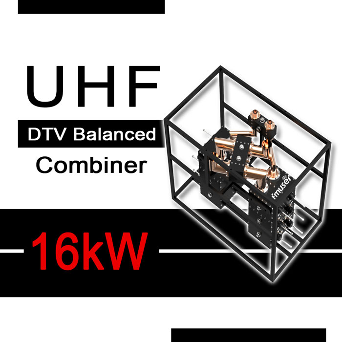
470-862 MHz 16kW 1 5/8" 3 1/8" Balanced CIB 6 Cavity Duplexer Compact DTV UHF Transmitter Combiner TX RX Duplexer for TV Station
FEATURES
- Price (USD): Please Contact Us
- Qty (PCS): 1
- Shipping (USD): Please Contact Us
- Total (USD): Please Contact Us
- Shipping Method: DHL, FedEx, UPS, EMS, By Sea, By Air
- Payment: TT(Bank Transfer), Western Union, Paypal, Payoneer
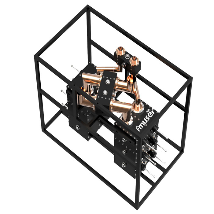
Main Features
- Copper, silver-plated brass, and high-quality aluminum alloy
- 6-cavity filters
- Low insertion loss and VSWR
- High isolation
- Compact design
- Convenient for multi-frequency integration
- The tailored design, multi-structure, and power combination
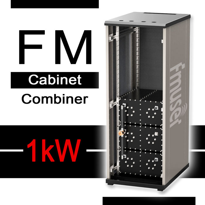
High Quality Transmitter Combiners Also in Stock
Starpoint (Branched) UHF Combiners Up to 20kW:
- 7/16 DIN 1kW 6 Cavities Solid State UHF Transmitter Combiner
- 7/16 DIN 1 5/8" 3 1/8" 700W to 6kW (customizable) Starpoint UHF Transmitter Combiner
- 15kW 20kW 3 1/8" 4 Cavity Starpoint UHF Transmitter Combiner
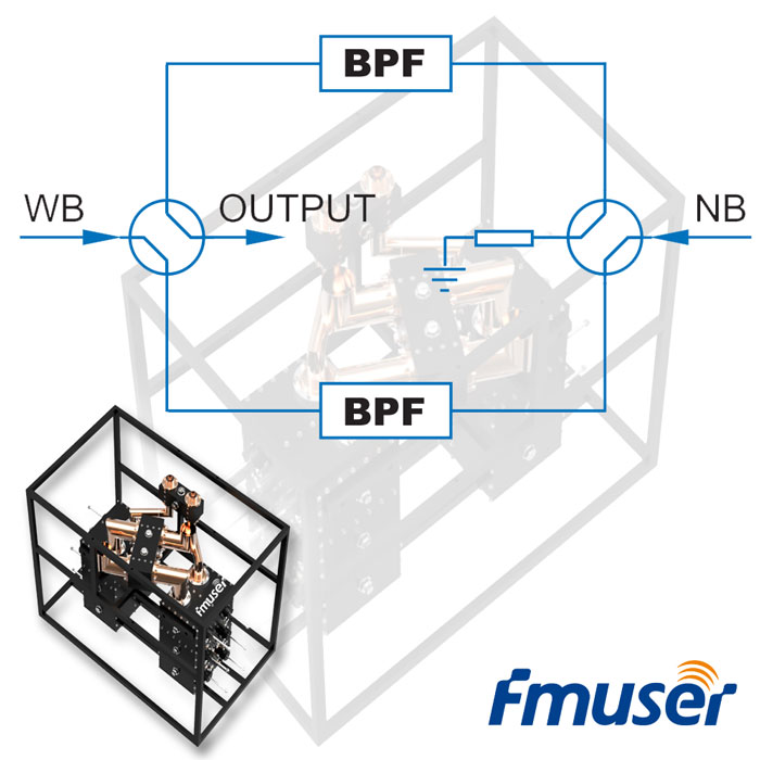
Balanced (CIB) UHF Combiners Up tp 120kW:
- 7/16 DIN 1kW DTV UHF Transmitter Combiner
- 1 5/8" 6kW 4 Way DTV UHF transmitter Combiner
- 1 5/8" 6 Cavity 1kW DTV UHF Transmitter Combiner
- 8kW UHF 4 Cavity 1 5/8" UHF Transmitter Combiner
- 1 5/8" 4 Cavity 8kW Balanced ATV UHF Transmitter Combiner
- 16kW 1 5/8" 3 1/8" Balanced CIB 6 Cavity UHF Transmitter Combiner
- 3 1/8" 6 Cavity 25kW Balanced CIB UHF Transmitter Combiner
- 25kW 4 1/2" Input 6 Cavity Solid State UHF Transmitter Combiner
Stretchline UHF Combiners:
Looking for more transmitter combiners for your broadcast station? Check these!
 |
 |
 |
 |
| FM Combiners | VHF Combiners | UHF Combiners | L Band Combiners |
- 16kW Banlanced UHF Digital TV Combiner x 1PCS
Please Contact Us for More Infomation
|
Model |
A |
B |
|
|---|---|---|---|
|
Configuration |
CIB |
CIB |
|
|
Frequency Range |
470 - 862 MHz |
470 - 862 MHz |
|
|
Min. Frequency Spacing |
0 |
0 |
|
|
Narrowband input |
|||
|
Max. Input Power |
3 kW * |
6 kW * |
|
|
VSWR |
≤ 1.1 |
≤ 1.1 |
|
|
Insertion loss |
f0 |
≤ 0.50 dB |
≤ 0.40 dB |
|
f0±3.8MHz |
≤ 1.50 dB |
≤ 1.40 dB |
|
|
f0±4.2MHz |
≥ 4 dB |
≥ 4 dB |
|
|
f0±6MHz |
≥ 35 dB |
≥ 35 dB |
|
|
f0±12MHz |
≥ 40 dB |
≥ 40 dB |
|
|
NB to WB isolation |
≥ 35 dB |
≥ 35 dB |
|
|
Wideband input |
|||
|
Max. Input Power |
6 kW RMS * |
16 kW RMS * |
|
|
VSWR |
≤ 1.1 |
≤ 1.1 |
|
|
Insertion loss |
≤ 0.1 dB |
≤ 0.1 dB |
|
|
WB to NB isolation |
≥ 40 dB |
≥ 40 dB |
|
|
Connectors |
1 5/8" |
1 5/8", 3 1/8" |
|
|
Number of cavities |
6 |
6 |
|
|
Dimensions |
800 × 405 × 710 mm |
1120 × 730 × 1070 mm |
|
|
Weight |
~ 76 kg |
~ 108 kg |
|
|
Notice: * TThe sum of NB and WB input power should be less than 16 kW. |
|||
Two Reasons Why RF Combiner is Used
Shortage of prime locations
As populations migrate to the suburbs, it has become more desirable to construct large broadcasting facilities which can reach these heavily populated areas from more central locations. Of course, these prime locations have become more valuable, so it makes sense to use each location to its fullest potential. This can best be done by sharing a transmitter site and a common antenna among several users. To accomplish this, the broadcast industry uses combiners of various types and sizes. For example, in San Francisco (Mt. Sutro), Toronto (CN Tower), Montreal (Mt. Royal), New York City (Empire State Building), and Chicago (John Hancock and Sears Buildings), tall towers or towers on skyscrapers have been used to consolidate as many broadcasting facilities as possible, including VHF-TV, UHF-TV, FM and land mobile communications services. This approach has proven very effective, not only using real estate economically but also spreading the tower costs over many users.
Group ownership of FM stations in a market has led to a proliferation of combined stations. And with the implementation of DTV systems, FM stations are being forced off existing towers, making it even more imperative that they share tower space, which increases the demand for combined systems.
The Requirements of FCC Isolation
When more than one signal is broadcast over a single antenna, the signals must be combined in such a way that no chance exists for the signals to feedback into each other’s transmitters. Failure to do so would allow intermodulation products to be generated within the final amplifier stages of the transmitters and broadcast over the antenna. These in- intermodulation products are generally referred to as “spurs.” Spurs created between FM stations can occur not only in the FM band but also within the low band VHF channels and above the FM band causing interference to the aviation band. In addition, FCC Rule 73.317(d) specifies that spurs more than G00 kHz removed from the carrier must be attenuated below the carrier frequency by 80 dB or by 43 + 10log10 (power in watts) dB, whichever is less. In practice, stations operating transmitter output powers of 5 kW or greater must usually meet the 80 dB requirement, while stations running lower TPOs (transmitter power outputs) fall under the computational method.
Experience has shown that to prevent spurs, each transmitter must be isolated from all others in the system by a minimum of 40 dB, with 4G to 50 dB ensuring regulatory compliance. Spur attenuation is accomplished by a combination of transmitter turn-around loss and filtering. Turn-around losses are inherent to the way spurs are created in the transmitter. These losses typically run in the G-13 dB range for tube-type transmitters, while 15-25 dB is typical for solid-state units. An off-frequency signal is attenuated 40 dB as it passes through the bandpass filters of the combiner module toward the transmitter with the spur it creates exiting the transmitter an additional G-25 dB below the level the signal entered. This spur is then attenuated 40 dB as it passes back through the bandpass filters. The result is spur attenuation of at least 80 dB, with 100 dB or more possible.
In today's world, the combiner has become an important part of the broadcast chain. It is important to realize it's technical and complexity. According to the advantages and disadvantages of the assembly, the system designer needs to choose specific applications. Correctly installed and correct tuning assemblies pass your signal to the far-stayed audience, and improper use of crosses can lead to reflections, resulting in poor health of the transmitter.
Why My RF combiner Stop Working
After years of continuous testing by the FMUSER technical team, we found that the common fault of the multiplexer is that the absorption resistance is burnt out.
In some bad weather environments (such as thunderstorms), the feeder system of the combiner is more vulnerable to the impact of lightning. At this time, the RF combiner is exposed to thunder, it may stop working, along with the burnout of multiple branch feeders. Several transmitters may have excessive reflection and high voltage drop, and the absorption resistance may also be burned out. The most effective solution is to replace the absorption resistor.
It is worth noting that there are different reasons to explain why your RF combiner stop working, which requires the RF technicians to treat it differently and remove the fault. Pay attention when the feeder fails or the reflection of the transmitter increases. Please check for times whether the RF combiner has abnormal temperature rise and whether the absorption load resistance is normal.
Four Extra Reasons to Explain Why Your RF Combiner Stop Working
During the routine maintenance, we also found that the absorption resistance was damaged and the resistance value became larger. In the middle of the work, we did not find that the transmitter reflected too much or dropped high voltage, and the VSWR of the antenna feeder was also normal. This has happened several times. After careful analysis, it is believed that the reasons may be various. The result is as follows.
- If the antenna feeder is abnormal, it will affect the working of the RF combiner. For example, the insulation resistance of the main feeder may become smaller; bad weather such as rain and snow will bring an instantaneous short circuit, open circuit, and a worse standing wave ratio to the antenna, all these factors will make some power reflect back.
- The index of the RF combiner becomes worse, the isolation of the 3dB directional coupler becomes low, and the bandpass filter becomes wide. According to the common principle, we know that there will be some leakage at the isolation end of the 3dB directional coupler, and it is impossible for the bandpass filter to reflect the out-of-band signal completely. When the power to the isolation end is so big as to exceeds the rated power of the absorption load, the temperature of the absorption load will rise and burn out finally.
- If the modulation is too large, the bandwidth of the RF signal becomes larger, and the power leaked to the absorption resistor increases. The transmitter exciter is generally not limited, and the early modulation system is often more than 130%.
- Some power will be transferred to the absorbing load due to the resonance frequency offset of the band-pass filter, carrier frequency offset of the transmitter, impedance mismatch between RF combiner and antenna, etc.
Advice from FMUSER: the damage of the absorption resistance may be caused by one or more reasons. If the absorption resistance is not replaced in time, the power borne by the absorption resistor will be reflected in the transmitter, which will cause greater harm.
What is Multiplexing and How it Works
The Passageway of Multiplexing RF Signals - RF Multiplexer
A multiplexer is a device that allows digital information from several sources to be routed onto a single line for transmission to a single destination. A demultiplexer does the reverse operation of multiplexing. It takes digital information from a single line and distributes it to a given number of output lines.
Multiplexing is the process of transmitting information from more than one source to a single signal by shared media. In any communication system that is either digital or analog, we need a communication channel for transmission. This channel can be a wired or a wireless link. It is not practical to allocate individual channels for each user.
Therefore a group of signals is combined together and sent over a common channel. For this we use multiplexers. We can multiplex simulations or digital signals. If an analog signal is multiplexed, this type of multiplexer is called an analog multiplexer. If the digital signal is multiplexed, this type of multiplexer is called a digital multiplexer.
Why RF Multiplexer is important?
We can transfer a large number of signals to a single medium. The channel can be a physical medium such as a shaft cable, a metal conductor, or a wireless link, and a plurality of signals must be processed once.
Therefore, the transfer cost can be reduced. Even if the transmission occurs on the same channel, they do not necessarily happen at the same time. Typically, multiplexing is a technique in which multiple message signals are combined into a composite signal so that these message signals can be transmitted on the common channel.
In order to transmit various signals on the same channel, the signal must be separated to avoid interference between them, and then they can easily separate them at the receiving end.
CONTACT US


FMUSER INTERNATIONAL GROUP LIMITED.
We are always providing our customers with reliable products and considerate services.
If you would like to keep touch with us directly, please go to contact us
-
![Home]()
Home
-
![Tel]()
Tel
-
![Email]()
Email
-
![Contact]()
Contact


