
Transmitter Combiners
A high power transmitter combiner is a device used in radio frequency (RF) systems to combine multiple RF signals into a single output with high power. It is essentially a network of RF power dividers and combiners arranged in such a way that individual input signals are combined and output through a single port.
The combiner works by using a series of passive components such as power dividers, directional couplers, filters, and amplifiers to distribute power between multiple input signals. The input signals are combined through the use of a power combiner, which is a device that uses the principle of superposition to add the individual input signals together. The combined signal is then amplified to reach the desired power level.

High power transmitter combiners are commonly used in applications such as broadcast radio and television, radar systems, satellite communications, and cellular networks. They offer improved efficiency, reliability, and cost-effectiveness by allowing multiple transmitters to share a single antenna, reducing the cost of infrastructure and improving overall system performance.
Complete High Power Transmitter Combiners Solution from FMUSER
Thanks to the world-class factory, FMUSER, as a leading broadcast equipment manufacturer, has successfully served all kinds of customers by providing reliable broadcast solutions for over 10 years, one thing is sure a high-power transmitter combiner with multiple inputs and outputs, is usually employed to broadcast multiple sets of FM programs with shared FM antennas.
Our Transmitter Combiner Works Well In:
- Professional broadcast stations at provincial, municipal, and township levels
- Medium and large broadcast stations with ultra-wide coverage
- Professional broadcast stations with millions of audience
- Radio operators who want to buy professional broadcast transmitters at a low cost
Here are high power transmitter combiners we provided so far:
- VHF CIB Combiners
- VHF Digital CIB Combiners
- VHF Starpoint Combiners
- UHF ATV CIB Combiners
- UHF DTV CIB Combiners
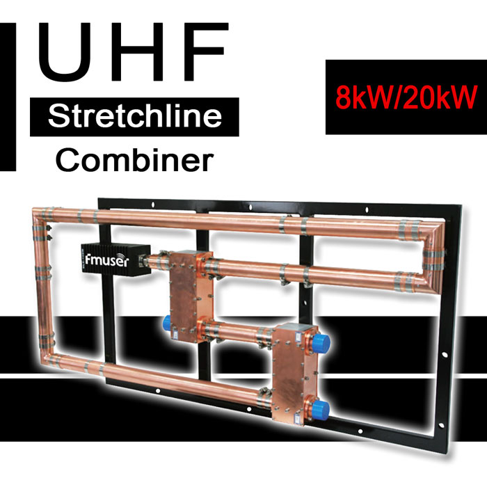
- UHF Stretchline Combiners
- UHF DTV Starpoint Combiners
- UHF ATV Starpoint Combiners
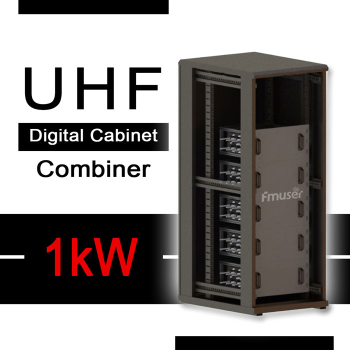
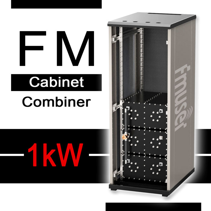
- UHF Digital CIB Combiner - Cabinet Type
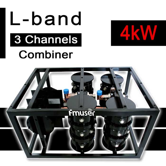
- L-Band Digital 3-channel Combiners
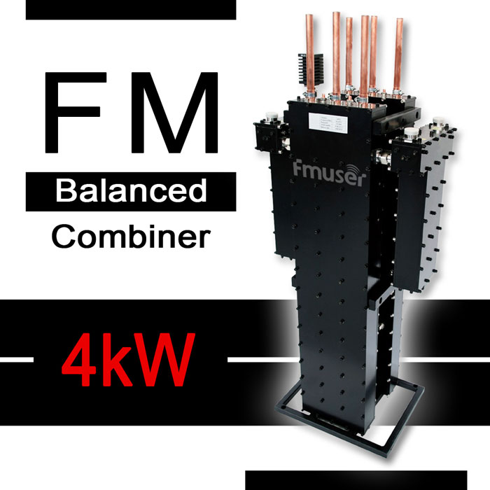
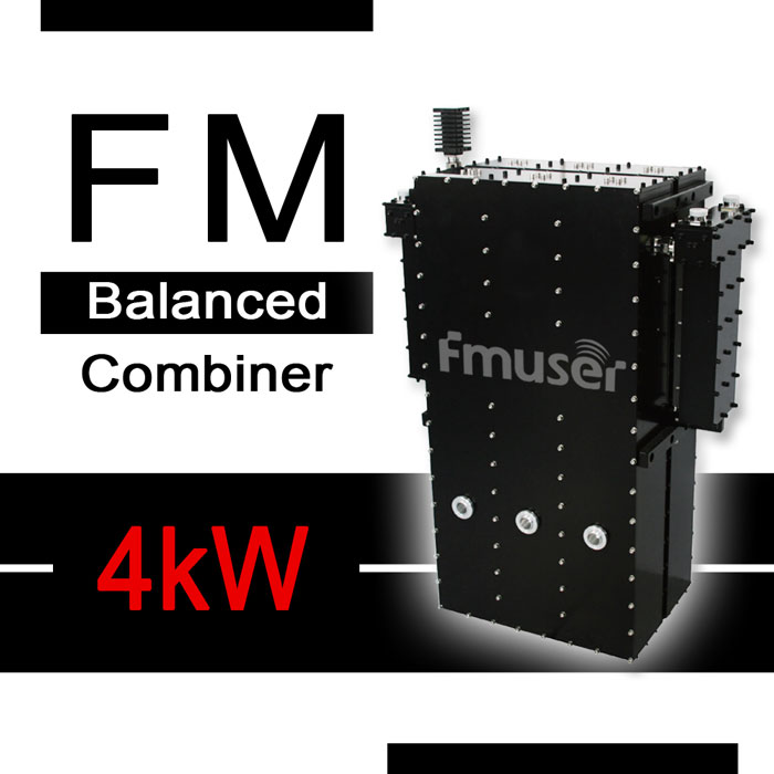
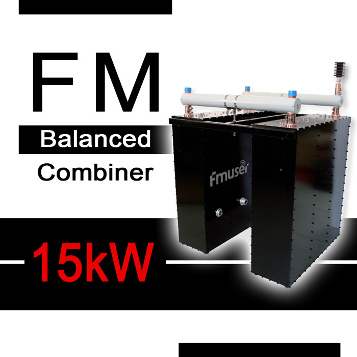
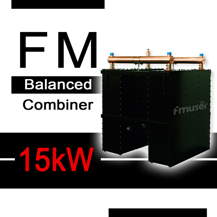
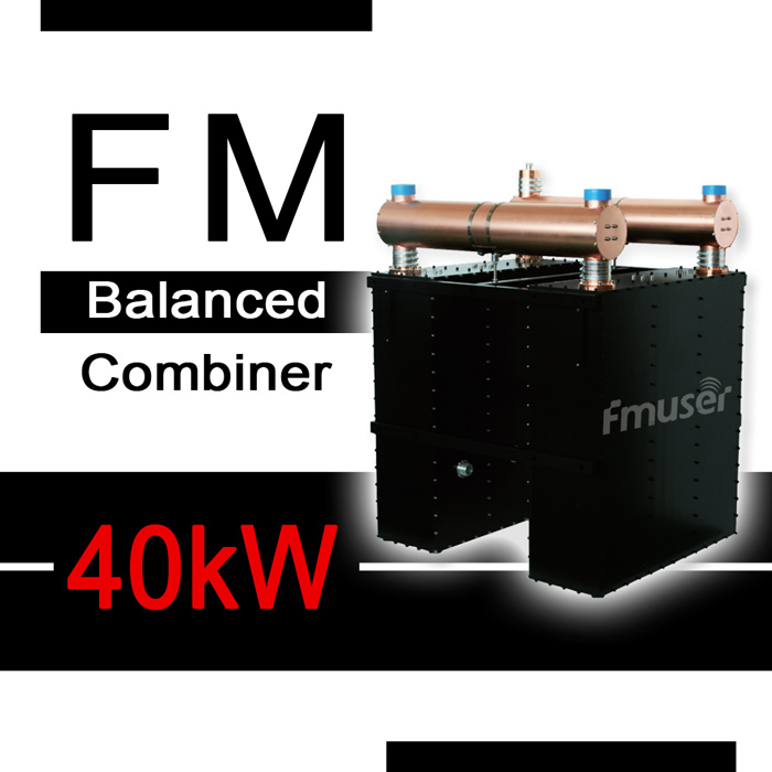
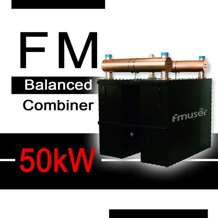
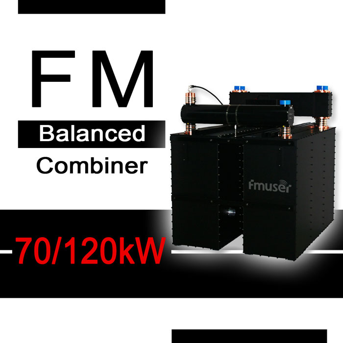
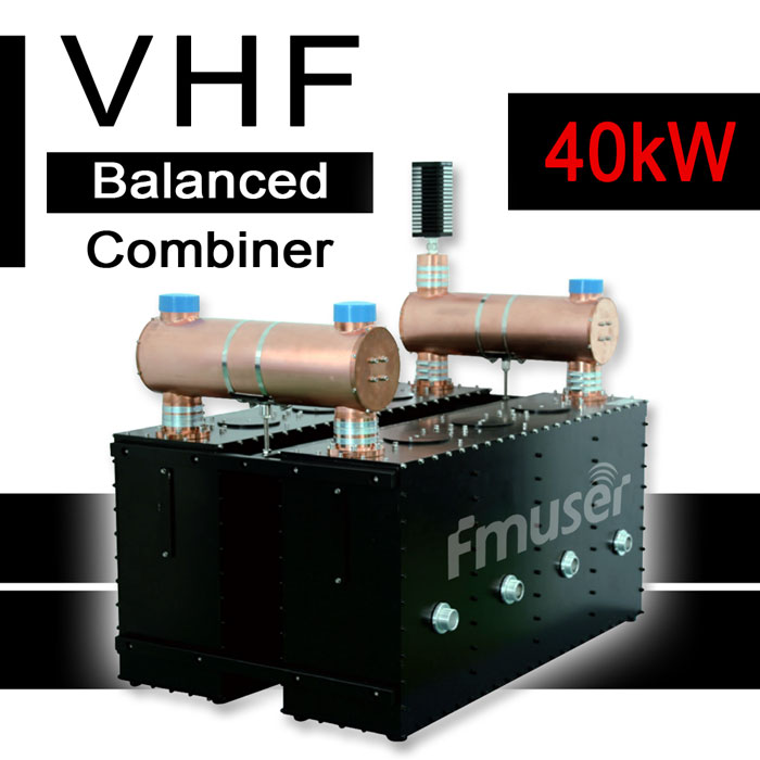
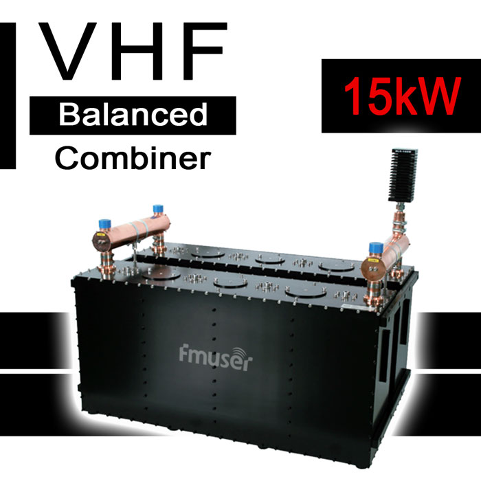
We have the best multi-channel FM combiners that power ranging from 4kW to 120kW, specifically, they are 4 kW, 15 kW, 40 kW, 50 kW, 70 kW, and 120 kW FM CIB combiners with 3 or 4 channels, available FM CIB combiners with multiple channels from FMUSER, and frequency with 87 -108MHz, well, they are also known as the FM balanced combiners, which is totally different from the star type combiners for sale.
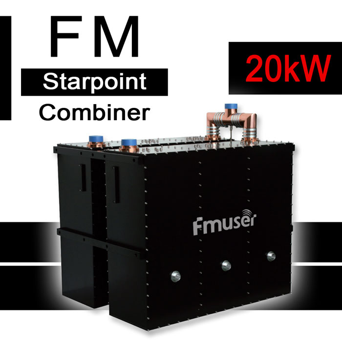
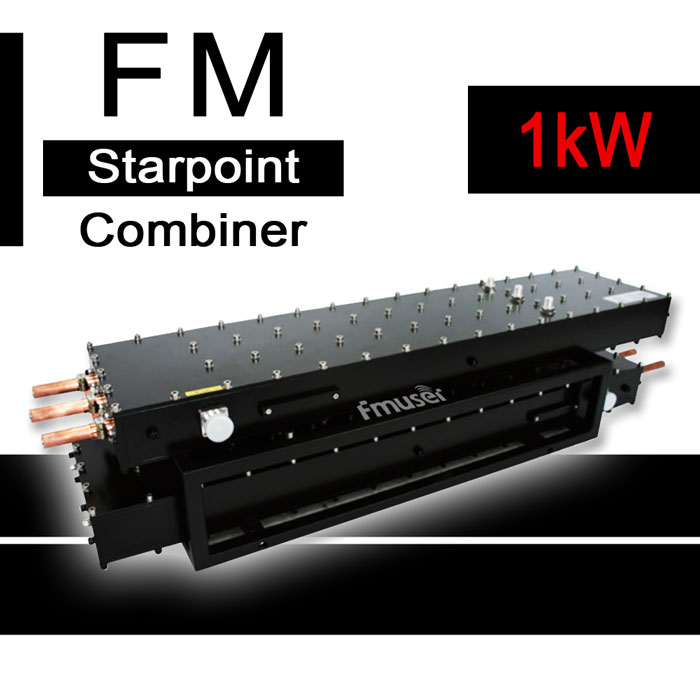
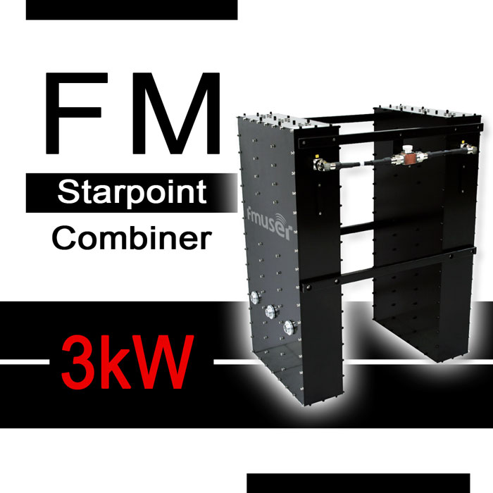
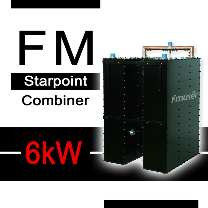
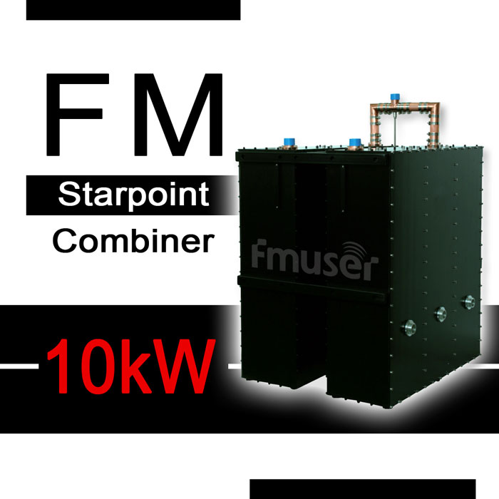
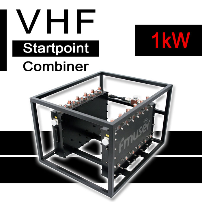
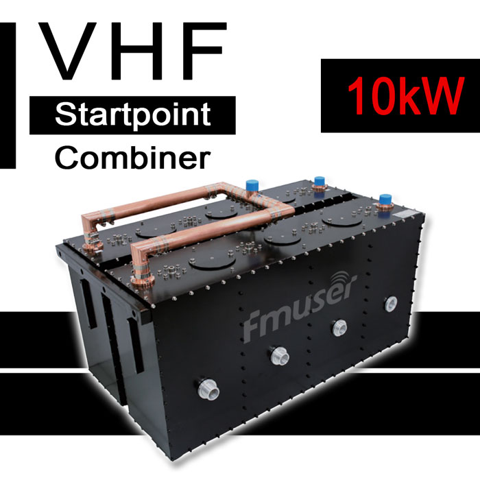
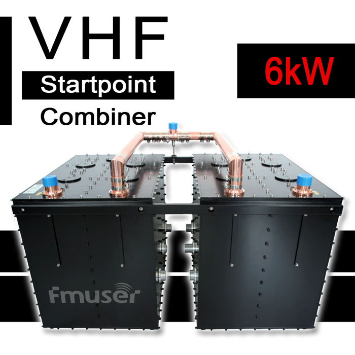
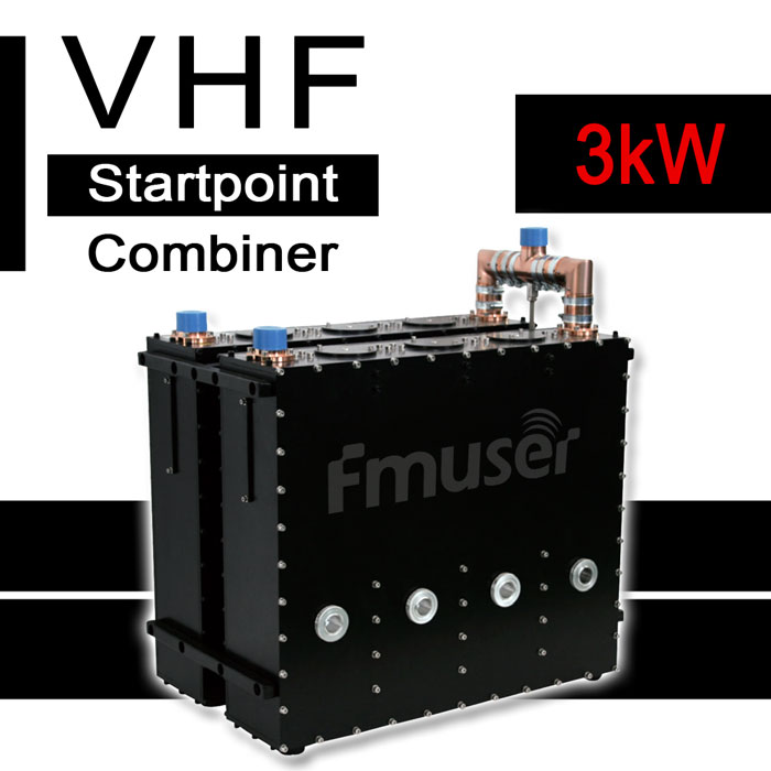
In exception to the balanced combiners, starpoint combiners are also one of the best-selling transmitter combiners types, power ranging from 1kW to 10kW, specifically, they are 1kW, 3kW, 6kW, 10kW FM Starpoint combiners with 3, 4, or 6 channels, and frequency with 87 -108MHz, these type of combiners are also known as star type combiners.
We also have the best multi-channel UHF/VHF TV combiners for sale, these combiners are 1 kW, 3 kW, 4 kW, 6 kW, 8 kW, 8/20 kW, 10 kW, 15 kW, 20kW, 15/20 kW, 24 kW, 25kW, 40 kW VHF/UHF TV combiners with 3, 4, 6 channels or dual-mode waveguide filters, some of them are the solid-state type or cabinet type combiner, some of them are L-band digital type combiners, but most of them are CIB combiners or star type (or Star point) combiners, with frequency ranging from 167 - 223 MHz, 470 - 862 MHz, 1452 - 1492 MHz.
View the following specification charts to choose the best transmitter combiners for you!
Chart A. CIB 4 kW Transmitter Combiners Price
The Next is FM Balanced Combiner for Sale | Skip
| Classification | Model | Power | Min. Frequency Spacing | Narrow Band Input | Max. Input Power | WideBand Input | Max. Input Power | Channel/Cavity | Visit for More |
| FM | A | 4 kW | 1.5 MHz | 1 kW | 3 kW | 3 | More | ||
| FM | A1 | 4 kW | 1 MHz * | 1 kW | 3 kW | 4 | |||
| FM | B | 4 kW | 1.5 MHz | 3 kW ** | 4 kW ** | 3 | More | ||
| FM | B1 | 4 kW | 0.5 MHz* | 3 kW ** | 4 kW ** | 4 | |||
|
Notice: * Combiner with frequency spacing less than 1 MHz can be customized ** The sum of NB and WB input power should be less than 4 kW |
|||||||||
Chart B. High Power FM CIB (balanced type) Combiner for Sale
The Previous is a 4kW High Power Transmitter Combiner Price | Skip
The Next is FM Starpoint Combiner for Sale | Skip
| Classification | Power | Model |
Channel/Cavity |
Min. Frequency Spacing | Narrow Band Input | Max. Input Power | WideBand Input | Max. Input Power | Visit for More |
| FM |
4 kW |
A | 3 | 1.5 MHz | 1 kW | 3 kW | More | ||
| A1 |
4 | 1 MHz * | 1 kW | 3 kW | |||||
| B | 3 | 1.5 MHz | 3 kW ** | 4 kW ** | More | ||||
| B1 | 4 | 0.5 MHz* | 3 kW ** | 4 kW ** | |||||
| 15 kW |
A | 3 | 1.5 MHz |
Narrow Band Input |
6 kW ** |
WideBand Input |
15 kW ** |
More | |
| A1 | 4 | 0.5 MHz* |
6 kW ** |
15 kW ** |
|||||
| B | 3 | 1.5 MHz |
10 kW ** |
15 kW ** |
More | ||||
| B1 | 4 | 0.5 MHz* |
10 kW ** |
15 kW ** |
|||||
| 40 kW |
A | 3 | 1.5 MHz |
Narrow Band Input |
10 kW | WideBand Input |
30 kW | More | |
| A1 | 4 | 0.5 MHz* |
10 kW | 30 kW | |||||
| 50 kW |
A |
3 | 1.5 MHz |
Narrow Band Input |
20 kW ** |
WideBand Input |
50 kW ** |
More | |
| A1 |
4 | 0.5 MHz* |
20 kW ** |
50 kW ** |
|||||
| 70 kW/120kW | A | 3 | 1.5 MHz* |
Narrow Band Input |
30 kW ** |
WideBand Input |
70 kW** | More | |
| 70 kW/120kW |
A1 | 3 | 1.5 MHz* |
30 kW ** |
120 kW** |
More |
|||
|
Notice: * Combiner with frequency spacing less than 1 MHz can be customized ** The sum of NB and WB input power should be less than 4 kW |
|||||||||
Chart C. High Power FM Starpoint Combiner Price
The Previous is CIB FM Combiner for Sale | Skip
The Next is Solid-State N-Channel Transmitter Combiner Price | Skip
| Classification | Power | Model |
Channel/Cavity |
Connectors | Min. Frequency Spacing | Max. Input Power | Visit for More |
| FM | 1 kW | A | 3 | 7-16 DIN |
3 MHz | 2 x 500 W | More |
| FM | 1 kW | A1 |
4 | 7-16 DIN |
1.5 MHz | 2 x 500 W | |
| FM | 3 kW | A | 3 | 7-16 DIN |
3 MHz | 2 x 1.5 kW | More |
| FM | 3 kW | A1 | 4 | 7-16 DIN |
1.5 MHz | 2 x 1.5 kW | |
| FM |
6 kW | A | 3 | 1 5/8" |
3 MHz |
2 x 3 kW |
More |
| FM |
6 kW |
A1 | 4 | 1 5/8" |
1.5 MHz |
2 x 3 kW |
|
| FM |
10 kW |
A | 3 | 1 5/8" |
3 MHz |
2 x 5 kW |
More |
| FM |
10 kW |
A1 | 4 | 1 5/8" |
1.5 MHz |
2 x 5 kW |
|
| FM | 20 kW |
A | 3 | 3 1/8" |
3 MHz |
2 x 10 kW | More |
| FM | 20 kW |
A1 | 4 | 3 1/8" |
1.5 MHz |
2 x 10 kW | |
|
Notice: * Combiner with frequency spacing less than 1 MHz can be customized ** The sum of NB and WB input power should be less than 4 kW |
|||||||
Chart D. Solid-State N-Channel Transmitter Combiner
The Previous is FM Star Type Combiner for Sale | Skip
The Next is UHF/VHF Balanced Combiner for Sale | Skip
| Classification | Power | Channel/Cavity |
Connectors | Min. Frequency Spacing | Max. Input Power | Visit for More |
| FM | 1 kW | 2 | 1 5/8" |
3 MHz | N x 1 W (N<5) | More |
Chart E. High Power CIB UHF/VHF Combiner for Sale
The Previous is Solid-State N-Channel Transmitter Combiner | Skip
The Next is VHF Branched Combiner Price | Skip
| Classification | Power | Model |
Channel/Cavity |
Min. Frequency Spacing | Narrow Band Input |
Max. Input Power | WideBand Input |
Max. Input Power | Visit for More |
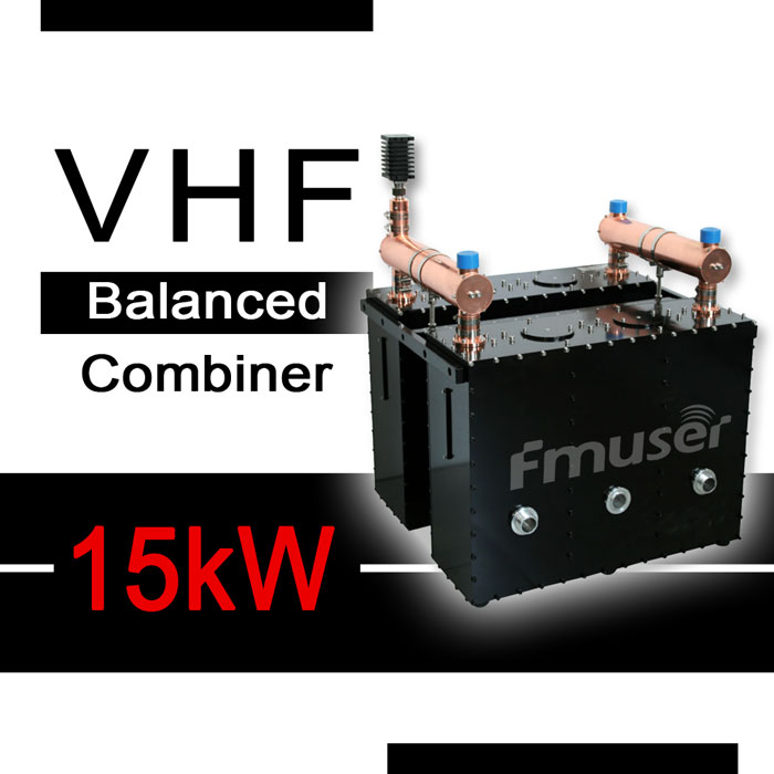
| VHF | 15 kW | A | 3 | 2 MHz | 6 kW * | 15 kW * | More | ||
| VHF | 15 kW | A1 |
4 | 1 MHz | 6 kW * | 15 kW * | |||
| VHF | 15 kW | B | 3 | 2 MHz | 10 kW * | 15 kW * | More | ||
| VHF | 15 kW | B1 | 4 | 1 MHz | 10 kW * | 15 kW * | |||
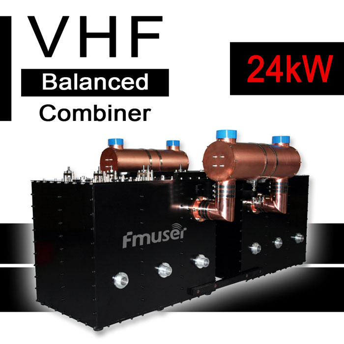
| VHF | 24 kW |
N/A | 6 | 0 MHz |
6 kW |
18 kW |
More | ||
| VHF | 40 kW | A | 3 | 2 MHz |
10 kW |
30 kW |
More | ||
| VHF | 40 kW | A1 | 4 | 1 MHz |
10 kW |
30 kW |
|||
|
Notice: * Combiner with frequency spacing less than 1 MHz can be customized ** The sum of NB and WB input power should be less than 4 kW |
|||||||||
Chart F. High Power VHF Starpoint Combiner Price
The Previous is UHF/VHF Balance Combiner for Sale | Skip
The Next is UHF ATV Balanced Combiner for Sale | Skip
| Classification | Power | Model |
Channel/Cavity |
Dimensions | Min. Frequency Spacing | Max. Input power | Isolation between Inputs | Visit for more |
| VHF | 3 kW | A | 4 | 650 × 410 × 680 mm |
2 MHz | 2 x 1.5 kW | ≥ 40 dB | More |
| VHF | 3 kW | A1 |
6 | 990 × 340 × 670 mm |
1 MHz | 2 x 1.5 kW | ≥ 55 dB | |
| VHF | 6 kW | A | 4 | L × 930 × H mm * |
2 MHz | 2 x 3 kW | ≥ 40 dB | More |
| VHF | 6 kW | A1 | 6 | L × 705 × H mm * |
1 MHz | 2 x 3 kW | ≥ 50 dB | |
| VHF | 10 kW |
A | 3 | L × 880 × H mm * |
4 MHz |
2 x 5 kW |
≥ 45 dB |
More |
| VHF | 10 kW | A1 | 4 | L × 1145 × H mm * |
2 MHz |
2 x 5 kW |
≥ 40 dB |
|
|
Notice: * L and H depend on channels. |
||||||||
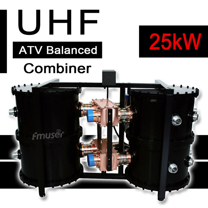
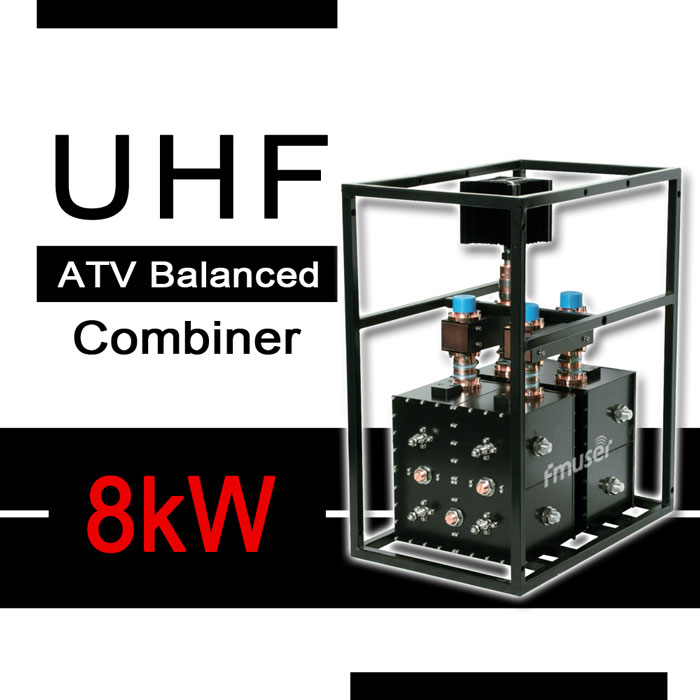
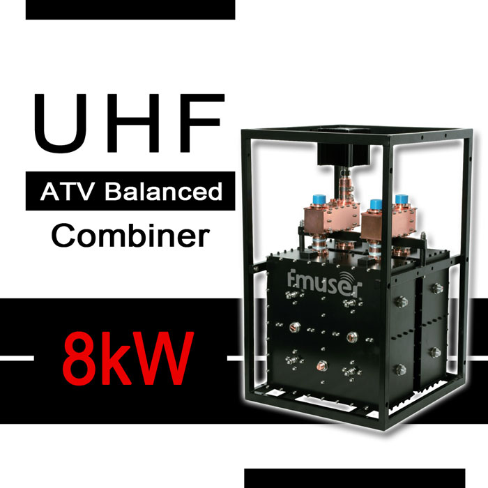
Chart G. High Power UHF ATV CIB Combiner for Sale
The Previous is VHF Starpoint Combiner for Sale | Skip
The Next is UHF DTV Balanced Combiner Price | Skip
| Classification | Power | Model |
Channel/Cavity |
Min. Frequency Spacing | Narrowband Input |
Max. Input power | Wideband Input |
Max. Input power |
Visit for more |
| UHF | 8 kW | A | 4 | 1 MHz | 2 kW * | 8 kW * | More | ||
| UHF | 25 kW | A | 4 | 1 MHz | 20 kW * | 25 kW * |
More |
||
| UHF | 25 kW | A1 | 6 | 1 MHz | 20 kW * | 25 kW * |
|||
|
Notice: * The sum of NB and WB input power should be less than 8 kW |
|||||||||
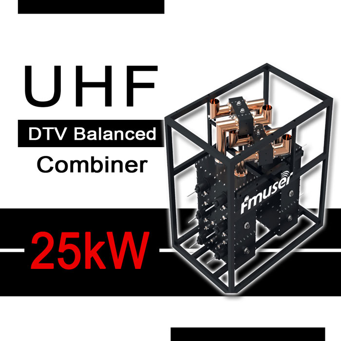
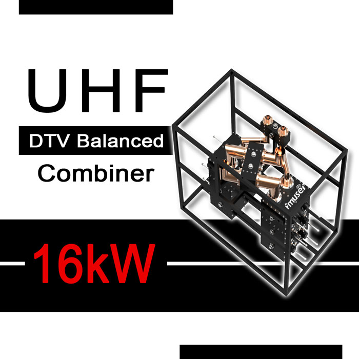
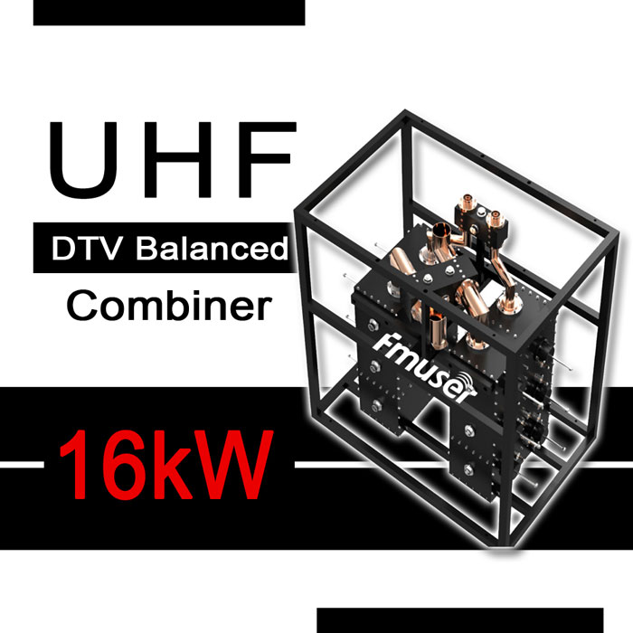
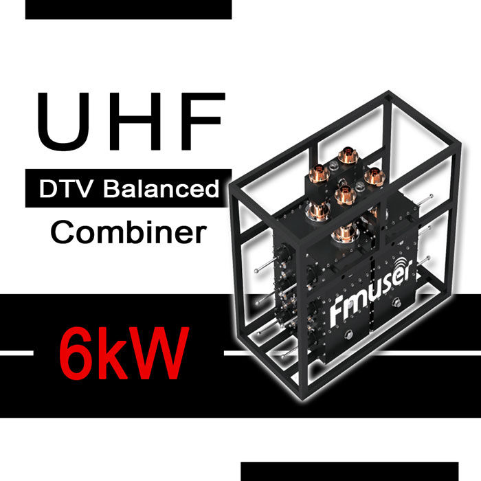
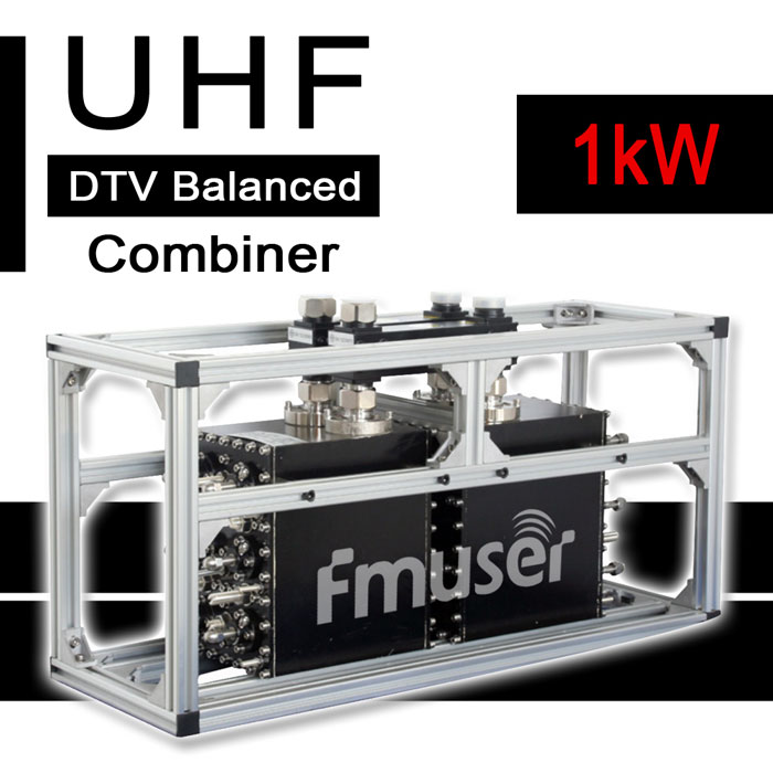
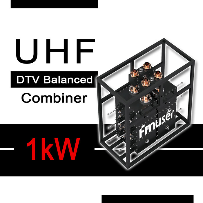
Chart H. High Power UHF DTV CIB Combiner for Sale
The Previous is UHF ATV Balanced Combiner for Sale | Skip
The Next is Solid-State UHF Digital Balanced Combiner Price | Skip
| Classification | Power | Model |
Channel/Cavity |
Min. Frequency Spacing | Narrowband Input |
Max. Input power | Wideband Input |
Max. Input power |
Visit for more |
| UHF | 1 kW | A | 6 | 0 MHz | 0.7 kW RMS * | 1 kW RMS * | More | ||
| UHF | 1 kW | B | 6 | 0 MHz | 1.5 kW RMS * | 6 kW RMS * |
More |
||
| UHF | 6 kW | A | 6 | 0 MHz | 3 kW RMS * | 6 kW RMS * |
More | ||
| UHF | 16 kW | A | 6 | 0 MHz | 3 kW RMS * | 16 kW RMS * |
More | ||
| UHF |
16 kW |
B | 6 | 0 MHz |
6 kW RMS * |
16 kW RMS * |
More | ||
| UHF |
25 kW |
A | 6 | 0 MHz | 6 kW RMS * |
25 kW RMS * |
More | ||
|
Notice: * The sum of NB and WB input power should be less than 8 kW |
|||||||||
Chart I. Solid-State UHF Digital Balance Combiner
The Previous is UHF DTV Balance Combiner Price | Skip
The Next is UHF DTV Star Type Combiner for Sale | Skip
| Classification | Power | Channel/Cavity |
Min. Frequency Spacing | Narrowband Input |
Max. Input Power | Wideband Input |
Max. Input Power |
Visit for More |
| UHF | 1 kW | 6 | 0 MHz | 0.7 kW RMS * | 1 kW RMS * |
More | ||
|
Notice: |
||||||||
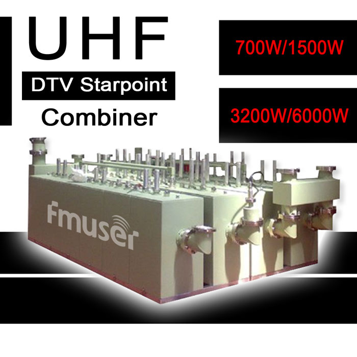
Chart J. High Power UHF DTV Starpoint Combiner for Sale
The Previous is Solid-State UHF Digital CIB Combiner | Skip
The Next is UHF ATV Starpoint Combiner Price | Skip
| Classification | Model |
Channel/Cavity |
Dimensions | Min. Frequency Spacing | Max. Input power | Connectors | Weight | Visit for More |
| UHF | A | 6 | 600 × 200 × 300 mm |
1 MHz | 2 x 350 W | 7-16 DIN | ~ 15 kg |
More |
| UHF | B |
6 | 800 × 350 × 550 mm |
1 MHz | 2 x 750 W | 1 5/8" | ~ 38 kg |
More |
| UHF | C | 6 | 815 × 400 × 750 mm |
1 MHz | 2 x 1.6 kW | 1 5/8" | ~ 57 kg |
More |
| UHF | D | 6 | 1200 × 500 × 1000 mm |
1 MHz | 2 x 3 kW | 1 5/8", 3 1/8" | ~ 95 kg |
More |
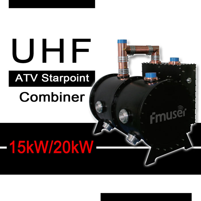
Chart K. High Power UHF ATV Starpoint Combiner Price
The Previous is UHF DTV Starpoint Combiner for Sale | Skip
The Next is UHF Stretchline Combiner for Sale | Skip
| Classification | Power | Model |
Channel/Cavity |
Dimensions | Min. Frequency Spacing | Max. Input power | Connectors | Weight | Visit for More |
| UHF | 20 kW | A | 4 | Depend on channels |
2 MHz | 2 x 10 kW | 3 1/8" | ~ 45 - 110 kg |
More |
| UHF | 15 kW | B | 4 | Depend on channels |
2 MHz | 10 kW / 5kW | 3 1/8" | ~ 65 - 90 kg |
More |
Chart L. High Power UHF Stretchline Combiner for Sale
The Previous is UHF ATV Starpoint Combiner Price | Skip
The Next is High Power L-band Digital 3-Channel Combiner | Skip
| Classification | Power | Model |
Insertion Loss |
Dimensions | Min. Frequency Spacing | Max. Input power | Connectors | Weight | Visit for More |
| UHF | 8 | A | ≤0.2 dB | 550 × 110 × H mm * |
5 MHz | 2 x 4 kW | 1 5/8" | Depend on channels |
More |
| UHF | 20 | B | ≤0.1 dB | 720 × 580 × H mm * |
5 MHz | 2 x 10 kW | 3 1/8" | Depend on channels |
More |
|
Notice: * H depends on channels |
|||||||||
Chart M. High Power L-band Digital 3-Channel Combiner
The Previous is UHF ATV Starpoint Combiner for Sale | Skip
Back to Chart A. 4 kW Transmitter Combiners Price | Skip
| Classification | Power | Channel/Cavity |
Min. Frequency Spacing | Max. Input Power |
Isolation between Inputs |
Weight | Dimensions | Visit for More |
| Improved CIB | 4 kW | 6 | 1 MHz | 3 x 1.3 kW |
≥ 60 dB |
~ 90 kg |
995 × 710 × 528 mm |
More |
FMUSER has been one of the leading broadcast equipment suppliers for over 10 years. Since 2008, FMUSER has created a working environment that fosters creative collaboration between a staff of highly skilled engineering developers and a meticulous manufacturing team. We have trading bussiness of high power transmitter combiners for sale in near 200+ countries and regions around the world, here are the ones from which you can buy transmitter combiners:
Afghanistan, Albania, Algeria, Andorra, Angola, Antigua and Barbuda, Argentina, Armenia, Australia, Austria, Azerbaijan, The Bahamas, Bahrain, Bangladesh, Barbados, Belarus, Belgium, Belize, Benin, Bhutan, Bolivia, Bosnia and Herzegovina, Botswana, Brazil, Brunei, Bulgaria, Burkina Faso, Burundi, Cabo Verde, Cambodia, Cameroon, Canada, Central African Republic, Chad, Chile, China, Colombia, Comoros, Congo, Democratic Republic of the, Congo, Republic of the, Costa Rica, Côte d’Ivoire, Croatia, Cuba, Cyprus, Czech Republic, Denmark, Djibouti, Dominica, Dominican Republic, East Timor (Timor - Leste), Ecuador, Egypt, El Salvador, Equatorial Guinea, Eritrea, Estonia, Eswatini, Ethiopia, Fiji, Finland, France, Gabon, The Gambia, Georgia, Germany, Ghana, Greece, Grenada, Guatemala, Guinea, Guinea - Bissau, Guyana, Haiti, Honduras, Hungary, Iceland, India, Indonesia, Iran, Iraq, Ireland, Israel, Italy, Jamaica, Japan, Jordan, Kazakhstan, Kenya, Kiribati, Korea, North, Korea, South, Kosovo, Kuwait, Kyrgyzstan, Laos, Latvia, Lebanon, Lesotho, Liberia, Libya, Liechtenstein, Lithuania, Luxembourg, Madagascar, Malawi, Malaysia, Maldives, Mali, Malta, Marshall Islands, Mauritania, Mauritius, Mexico, Micronesia, Federated States of, Moldova, Monaco, Mongolia, Montenegro, Morocco, Mozambique, Myanmar (Burma), Namibia, Nauru, Nepal, Netherlands, New Zealand, Nicaragua, Niger, Nigeria, North Macedonia, Norway, Oman, Pakistan, Palau, Panama, Papua New Guinea, Paraguay, Peru, Philippines, Poland, Portugal, Qatar, Romania, Russia, Rwanda, Saint Kitts and Nevis, Saint Lucia, Saint Vincent and the Grenadines, Samoa, San Marino, Sao Tome and Principe, Saudi Arabia, Senegal, Serbia, Seychelles, Sierra Leone, Singapore, Slovakia, Slovenia, Solomon Islands, Somalia, South Africa, Spain, Sri Lanka, Sudan, Sudan, South, Suriname, Sweden, Switzerland, Syria, Taiwan, Tajikistan, Tanzania, Thailand, Togo, Tonga, Trinidad and Tobago, Tunisia, Turkey, Turkmenistan, Tuvalu, Uganda, Ukraine, United Arab Emirates, United Kingdom, United States, Uruguay, Uzbekistan, Vanuatu, Vatican City, Venezuela, Vietnam, Yemen, Zambia, Zimbabwe
Through this spirit of and dedication to true collaboration, FMUSER has been able to create some of the most innovative electronic components, utilizing the time-tested principles of yesterday and incorporating the advanced science of today.

One of our proudest achievements, as well as a popular choice of our many clients, is our high power transmitter combiners for the broadcast transmitter stations.
"You may find some good stuff from FMUSER. They cover all ranges of power for the Transmitter Combiner, best FM Combiner for sale, power ranging from 4kw to 15kw, 40kw to 120kw"
- - - - - James, loyal member of FMUSER
-
![470-862 MHz 7/16 DIN 1kW Solid State UHF Transmitter Combiner Starpoint Compact 1000W 6 Cavity Duplexer for TV Broadcasting]()
Price(USD):Ask for a quotation
Sold:11
-
![87-108 MHz 4kW Compact TX RX Systems Duplexer RF Channel Combiner with 3 or 4 Cavities and 7-16 DIN Input for FM Broadcasting]()
Price(USD):Ask for a quotation
Sold:4
-
![87-108 MHz 4kW FM Combiner Solid State Duplexer Balanced CIB FM Transmitter Combiner with 3/4 Cavities for FM Radio Station]()
Price(USD):Ask for a quotation
Sold:4
-
![1452-1492 MHz 1 5/8" 6 Cavity 4kW L Band RF Combiner Compact Digital 3 Channel Combiner Solid-state RF Triplexer for TV Station]()
Price(USD):Ask for a quotation
Sold:2
-
![87-108 MHz 15kW FM Combiner 3 or 4 Cavity Vari Notch Duplexer Solid State FM Transmitter Combiner with 1 5/8" Input for FM Radio]()
Price(USD):Ask for a quotation
Sold:3
-
![470-862 MHz 8kW/20kW Stretchline UHF Transmitter Combiner Tunable RF Channel Combiner with 1 5/8" 3 1/8" Input for TV Station]()
Price(USD):Ask for a quotation
Sold:9
-
![87-108 MHz 15kW Compact TX RX Combiner 4 Cavity Duplexer Solid-state FM Transmitter Combiner with 1 5/8" Input for FM Broadcast]()
Price(USD):Ask for a quotation
Sold:7
-
![87-108MHz 40kW Compact RF Power Combiner with 3 1/8" Input Solid-state FM CIB Balanced Duplexer for Signal Combiner Two Antennas]()
Price(USD):Ask for a quotation
Sold:10
-
![87-108 MHz 50kW 3/4 Cavities FM Transmitter Combiner Solid State Duplexer with 3 1/8" Input High Power TX Combiner for FM Radio]()
Price(USD):Ask for a quotation
Sold:10
-
![87-108 MHz 70kW/120 kW FM Combiner High Power Balanced CIB FM Transmitter Combiner 3 Cavity Duplexer for FM Radio Station]()
Price(USD):Ask for a quotation
Sold:4
-
![87-108 MHz 1kW 1 5/8" 2 Cav. N-Channel FM Starpoint Combiner Radio Repeater Duplexer High Power Radio Combiner for FM Station]()
Price(USD):Ask for a quotation
Sold:11
-
![87-108 MHz 2-Way 3 1/8" 20kW Starpoint FM Transmitter Combiner with 3 or 4 Cavities Compact tx rx duplexer for FM Radio Station]()
Price(USD):Ask for a quotation
Sold:3
-
![87-108MHz 7-16 DIN 1kW Starpoint FM Transmitter Combiner Compact 4 Cavity Duplexer with Inner Duplexer Filter for FM Broadcast]()
Price(USD):Ask for a quotation
Sold:13
-
![87-108MHz 7-16 DIN 3kW Branched Type FM Combiner Solid-state 2 Way Starpoint Cavity Duplexer with 3 or 4 Cavity for FM Station]()
Price(USD):Ask for a quotation
Sold:13
-
![87-108MHz 6kW Starpoint FM Combiner 2 way RF Combiner Star Type Radio Duplexer with 1 5/8" Input and 3/4 Cavities for FM Station]()
Price(USD):Ask for a quotation
Sold:4
-
![87-108MHz 10kW 3 or 4-Cavity Starpoint FM Transmitter Combiner Compact 2 Way Cavity Duplexer with 1 5/8" Input for FM Station]()
Price(USD):Ask for a quotation
Sold:7
-
![167-223 MHz 4 or 6 Cav. 7/16 DIN 1kW Starpoint VHF Transmitter Combiner Compact 6 Cavity Duplexer TX RX Duplexer for TV Station]()
Price(USD):Ask for a quotation
Sold:3
-
![167-223 MHz 3 1/8" 3 or 4 Cav. 40kW Compact VHF TX RX Combiner Balanced VHF Cavity Duplexer 3 Way RF Combiner for TV Station]()
Price(USD):Ask for a quotation
Sold:3
-
![167-223 MHz 3 1/8" 24kW Compact VHF 6 Cavity Duplexer Digital Balanced VHF Transmitter Combiner TX RX Duplexer for TV Broadcast]()
Price(USD):Ask for a quotation
Sold:4
-
![167-223MHz 1 5/8" 3 or 4 Cavity 15kW VHF Transmitter Combiner Compact VHF Cavity Duplexer TX RX Balanced Duplexer for TV Station]()
Price(USD):Ask for a quotation
Sold:9
-
![167-223 MHz 1 5/8" 3 or 4 Cav. 15kW Balanced VHF Transmitter Combiner Compact Radio Combiner VHF Cavity Duplexer for TV Station]()
Price(USD):Ask for a quotation
Sold:4
-
![167-223 MHz 1 5/8" 4 Cav. VHF Starpoint 10kW Transmitter Combiner Compact Cavity Duplexer for VHF Combiner Multicoupler System]()
Price(USD):Ask for a quotation
Sold:9
-
![167-223 MHz 4 or 6 Cav. 1 5/8" 6kW TX RX Combiner Compact 2 Way RF Combiner Starpoint VHF Duplexer Repeater for TV Station]()
Price(USD):as
Sold:6
-
![167-223 MHz 1 5/8" 4/6 Cav. 3kW VHF Starpoint Transmitter Combiner Compact Filter Combiner TX RX Systems Duplexer for TV Station]()
Price(USD):Ask for a quotation
Sold:3
-
![470-862 MHz 3 1/8" 6 Cavity 25kW Balanced CIB UHF Transmitter Combiner ATV TV TX RX Duplexer Compact UHF Combiner for TV Station]()
Price(USD):Ask for a quotation
Sold:7
-
![470-862MHz 25kW 4 1/2" Input Compact UHF RF Combiner High Power UHF 6 Cavity Duplexer Solid State DTV TX Combiner for TV Station]()
Price(USD):Ask for a quotation
Sold:7
-
![470-862 MHz 15kW 20kW 3 1/8" Starpoint UHF Transmitter Combiner Analog TX RX Combiner Compact 4 Cavity Duplexer for TV Station]()
Price(USD):Ask for a quotation
Sold:7
-
![470-862 MHz Starpoint UHF Transmitter Combiner 6 Cavity Duplexer 7/16 DIN 1 5/8" 3 1/8" Supported 700W to 6kW Customized Power]()
Price(USD):Ask for a quotation
Sold:4
-
![470-862 MHz 8kW UHF 4 Cavity Duplexer 1 5/8" Compact TX Combiner Channel Plus High Power UHF Transmitter Combiner for TV Station]()
Price(USD):Ask for a quotation
Sold:2
-
![470-862 MHz 16kW 1 5/8" 3 1/8" Balanced CIB 6 Cavity Duplexer Compact DTV UHF Transmitter Combiner TX RX Duplexer for TV Station]()
Price(USD):Ask for a quotation
Sold:2
-
![470-862MHz 1 5/8" 3 1/8" 6 Cavity 16kW Balanced Radio Combiner 2 Way RF Combiner Compact Radio Frequency Combiner for TV Station]()
Price(USD):Ask for a quotation
Sold:9
-
![470-862 MHz 1 5/8" 4 Cavity 8kW Balanced Duplexer Compact ATV UHF Transmitter Combiner Solid state Duplexer for TV Broadcast]()
Price(USD):Ask for a quotation
Sold:7
-
![470-862 MHz 1 5/8" 6kW Compact UHF Cavity Duplexer 4 Way RF Combiner High Power DTV UHF transmitter Combiner for TV Broadcasting]()
Price(USD):Ask for a quotation
Sold:9
-
![470-862 MHz 7/16 DIN 1kW UHF TV Combiner Compact Balanced RF Signal Combiner Solid State DTV UHF Cavity Duplexer for TV Station]()
Price(USD):Ask for a quotation
Sold:4
-
![470-862 MHz 1 5/8" 6 Cavity Solid State 1kW DTV UHF Transmitter Combiner Compact Radio Repeater Duplexer Filter for TV Broadcast]()
Price(USD):Ask for a quotation
Sold:6
- Full Terminology List to High Power Transmitter Combiners
- Here are some additional terminologies related to high power transmitter combiners and their explanations:
1. Number of Cavities: The number of cavities in a combiner refers to the number of resonant circuit cavities within the combiner. Each cavity is designed to operate as a resonant circuit that couples energy from the input to the output port of the combiner. The power handling capability and isolation level of the combiner increase with the number of cavities.
2. Frequency: The frequency of a combiner indicates the operating frequency band of the combiner. There are different frequency bands for different types of broadcasting operations, such as UHF (Ultra High Frequency), VHF (Very High Frequency), FM (Frequency Modulation), TV, and L-band. The frequency band determines the range of frequencies the combiner can handle.
3. Input Power: Input power defines the maximum power that the combiner can handle without any damage. The input power rating is usually expressed in kilowatts (kW) and indicates the maximum power that the combiner can withstand.
4. Configuration: There are different types of configurations for high power transmitter combiners, including star-point, CIB (Close-Input Band), and Stretchline. The configuration defines the way the input signals are combined together and how they are distributed to the output ports of the combiner.
5. Frequency or Channel Spacing: Frequency or channel spacing is defined as the minimum frequency difference between two adjacent channels. This parameter is critical in combiner design to mitigate intermodulation distortion (IMD).
6. Insertion Loss: Insertion loss is the amount of signal loss that occurs as a signal passes through the combiner. It is expressed in decibels (dB) as a negative value. Lower insertion loss indicates better signal passing capability, and it is important to minimize to avoid signal degradation.
7. VSWR: Voltage Standing Wave Ratio (VSWR) is a measure of how efficiently the combiner transfers energy from the input signal to the output signal. A lower VSWR value indicates better energy transfer efficiency.
8. Isolation: Isolation is the amount of separation between two signals. It is expressed in decibels (dB) and indicates the degree to which the input and output signals can be isolated to prevent interference.
9. Connector Types: Connector types refer to the type and size of connector used for the input and output connections of the combiner. Common connector types for high power transmitter combiners include 7/16 DIN, 1-5/8", 3-1/8", and 4-1/2".
10. Coupling: The coupling parameter of a combiner refers to the amount of energy transferred from the input signal to the output signal. Coupling is measured in decibels (dB), and a combiner’s coupling can be fixed or variable, depending on the design.
11. Wideband vs. Narrowband: A wideband combiner can handle a broader range of frequencies, while a narrowband combiner is designed to operate within a specific frequency band.
12. Passband: The passband of a combiner refers to the frequency range within which the combiner will allow the input signals to pass through and be combined.
13. Stopband: The stopband of a combiner refers to the frequency range within which the combiner will attenuate or block incoming signals.
14. Group Delay: Group delay is a measure of the time delay that input signals experience as they pass through the combiner. An ideal combiner would not introduce any group delay, but in practice, some group delay is typically present.
15. Harmonics: Harmonics are signals generated at frequencies that are integer multiples of the input frequency. A good combiner will suppress any harmonic signals that may be generated by the input signals.
17. PIM (Passive Intermodulation): PIM is the distortion of signals that can occur when two or more signals pass through a passive component such as a combiner. A properly designed and maintained combiner will minimize the risk of PIM occurring.
18. Spurious Signals: Spurious signals are signals that are not intended to be transmitted, and can cause interference with other communication channels. Combining unwanted signals can lead to spurious signals and degradation of the transmitted signal.
These are important parameters to consider when selecting and designing high power transmitter combiners for optimal broadcasting performance. Understanding these parameters is essential for proper selection, design, and maintenance of a combiner for optimal broadcasting performance.
- What does the cavities number means to a high power transmitter combiner?
- The number of cavities in a high power transmitter combiner refers to the number of resonant circuit cavities within the combiner. The cavities are usually cylindrical or rectangular metal tubes, each with a specific resonant frequency within the frequency band of the combiner.
Each cavity is designed to operate as a resonant circuit that couples energy from the input to the output ports of the combiner. By adjusting the length and diameter of the cavities, the resonant frequency of each cavity can be precisely tuned to the specific frequency of the input signal.
In a high power transmitter combiner, the number of cavities is important as it determines the combiner's power handling capabilities and the level of isolation between the input and output signals. The more cavities a combiner has, the higher the power handling capability, and the better the isolation between the signals. However, the more cavities in a combiner, the more complex it becomes, and the more difficult it is to tune and maintain.
In summary, the number of cavities in a high power transmitter combiner is important as it determines the power handling capability and isolation level of the combiner, as well as its complexity and tuning requirements.
- What kind of broadcast equipment is needed to build up a complete antenna system?
- The equipment required to build up a complete antenna system for a radio broadcasting station varies depending on the type of station. However, the following is a general list of equipment that may be required for UHF, VHF, FM, and TV broadcasting stations:
UHF Broadcasting Station:
- High power UHF transmitter
- UHF combiner (to combine multiple transmitters into a single output)
- UHF antenna
- UHF filter
- UHF coaxial cable
- UHF dummy load (for testing)
VHF Broadcasting Station:
- High power VHF transmitter
- VHF combiner (to combine multiple transmitters into a single output)
- VHF antenna
- VHF filter
- VHF coaxial cable
- VHF dummy load (for testing)
FM Radio Station:
- High power FM transmitter
- FM combiner (to combine multiple transmitters into a single output)
- FM antenna
- FM filter
- FM coaxial cable
- FM dummy load (for testing)
TV Broadcasting Station:
- High power TV transmitter
- TV combiner (to combine multiple transmitters into a single output)
- TV antenna (VHF and UHF)
- TV filter
- TV coaxial cable
- TV dummy load (for testing)
Additionally, for all of the above broadcasting stations, the following equipment may also be required:
- Tower or mast (to support the antenna)
- Guy wires (to stabilize the tower or mast)
- Grounding system (to protect the equipment from lightning strikes)
- Transmission line (to connect the transmitter to the antenna)
- RF meter (to measure signal strength)
- Spectrum analyzer (to monitor and optimize the signal)
- What are the applications of a high power transmitter combiner?
- A high power transmitter combiner has various applications in RF (radio frequency) systems where multiple RF transmitters need to connect to a single antenna. Here are some common applications of a high power transmitter combiner:
1. Broadcast Radio and TV: In radio and television broadcasting, a combiner is used to combine multiple RF signals from different transmitters into a single output to feed a shared antenna. This reduces the need for multiple antennas and transmission lines which increases the cost of the installation and reduces the efficiency of transmission.
2. Mobile Communications: In mobile communication networks, a combiner is used to combine multiple RF signals from base stations into a single output signal that is transmitted through a common antenna. This enables network operators to optimize network coverage and increase capacity.
3. Radar Systems: In radar systems, a combiner is used to combine multiple RF signals from different radar modules into a single output to improve the resolution and quality of the radar image.
4. Military Communications: A combiner is used in military communications systems to combine signals from different transmitters onto one antenna, making it more efficient and cost-effective to operate in the field.
5. Satellite Communications: In satellite communications, a combiner is used to combine signals from multiple transponders, which are then transmitted to earth stations via a single antenna. This reduces the size and weight of the satellite and improves the efficiency of the communication system.
In summary, high power transmitter combiners offer an efficient and cost-effective way to combine multiple RF signals into a single output in various communication systems such as broadcast radio and TV, mobile communications, radar systems, military communications, and satellite communications.
- What are the synonyms of high power transmitter combiner?
- There are several synonyms for the term "high power transmitter combiner" in the field of radio frequency (RF) engineering. They include:
1. Power Combiner
2. Transmitter Combiner
3. Amplifier Combiner
4. High-Level Combiner
5. RF Combiner
6. Radio Frequency Combiner
7. Signal Combiner
8. Multiplexer Combiner
9. Splitter-Combiner
All these terms are used interchangeably to describe a device that combines multiple RF signals into a single high-powered output signal.
- What are different types of high power transmitter combiners?
- Here are detailed explanations of some of the most common configurations or types of combiners used in broadcasting stations:
1. Starpoint Combiner (Starpoint or Star-Type Configuration): A starpoint configuration, also referred to as a star-type configuration, is a combiner configuration where all the inputs are combined at a central point. This configuration is commonly used for broadcasting applications with multiple input signals, such as a television station or a data center. The advantage of a starpoint configuration is that it accommodates a large number of input signals, while maintaining good isolation between them. In a starpoint combiner, multiple transmitter inputs are connected to a single point in the center of the combiner, which then feeds a common output. The combiner uses coaxial lines, hybrid couplers, and resistors to combine the signals. Starpoint combiners are commonly used in FM radio stations.
2. Branched-Type Configuration: A branched-type configuration is a combiner configuration where the inputs are split, or branched out, to several parallel circuits. This configuration is commonly used for high power transmitter combiners that have a large number of input signals and high power ratings. The advantage of the branched-type configuration is that it allows for easier expansion and replacement of input signals or modules.
3. Balanced Type Combiner (AKA CIB: Close-Input Band) or Balanced Configuration: The CIB or balanced configuration is a combiner configuration where the input signals are paired and combined in a balanced manner. This configuration improves power handling and prevents reflected power by balancing the impedance of each input. A CIB combiner uses a center-fed dipole or a folded dipole as the common element. The dipole is connected to multiple input ports from each transmitter and combines the signals through impedance matching and balancing networks. CIB combiners are used in UHF and VHF broadcasting stations.
4. Stretchline Configuration: The Stretchline configuration is a combiner configuration that uses balanced input lines and microstrip or stripline filters. This configuration is commonly used in high power transmitter combiners for UHF and VHF applications. The Stretchline configuration provides good power handling capability and is well suited for narrowband, high coupling applications. A stretchline combiner uses transmission line elements such as quarter-wave transformers and impedance transformers to combine multiple RF inputs. The signals are combined in a serial configuration along a single transmission line. Stretchline combiners are used in VHF and UHF broadcasting stations.
5. Hybrid Combiner: A hybrid combiner uses hybrid couplers to combine two or more signals. A hybrid coupler splits an input signal into two output signals with a predetermined phase difference. The input signals are combined in phase by feeding them into the hybrid coupler at the correct phase angle. Hybrid combiners are used in both FM and TV broadcasting stations.
6. Bandpass Filter Combiner: A bandpass filter combiner is a type of combiner that uses bandpass filters to allow only the desired frequency ranges to pass through. The individual signals from each transmitter are passed through the filters before being combined. This combiner is used in VHF and UHF broadcasting stations.
In summary, high power transmitter combiners are used to combine multiple RF signals into a single output. The type of combiner used depends on the broadcasting station's specific requirements. The most common types are starpoint, stretchline, balanced type (CIB), hybrid, and bandpass filter combiners. All combiners typically use passive components such as resistors, hybrid couplers, and bandpass filters to combine the individual signals. The configuration of a combiner is an important factor in its design and application. Different configurations can offer advantages such as improved power handling, isolation and expansion, while other configurations are better suited for narrowband or high coupling applications. Selecting the right configuration depends on the specific requirements of the broadcasting application.
- Why a high power transmitter combiner is needed for broadcasting?
- A high-power transmitter combiner is needed for broadcasting because it allows multiple transmitters to send signals through a single antenna. This is necessary because a single transmitter may not have enough power to reach all of the intended receivers. By combining the power of multiple transmitters, broadcasters can achieve greater coverage and reach a wider audience.
A high-quality high-power transmitter combiner is important for a professional broadcasting station because it ensures that the combined signals are clean and interference-free. Any distortions or interference in the combined signal can result in poor-quality audio or video, which can be detrimental to the broadcaster's reputation. Additionally, a high-quality combiner can improve the efficiency of the system, allowing broadcasters to transmit at higher power levels without losing signal integrity. This is particularly important in crowded urban areas where many different broadcasters are vying for the same frequencies. A robust and reliable combiner can help ensure that each broadcaster's signal is heard loud and clear.
- What are the most important specifications of a high power transmitter combiner?
- The most important specifications of a high-power transmitter combiner include:
1. Power handling capacity: This is the maximum amount of power that the combiner can handle without damaging the equipment or causing interference with other signals. It is usually measured in kilowatts (kW).
2. Frequency range: The combiner must be able to operate over the frequency range used by the transmitter and antenna.
3. Insertion loss: This is the amount of signal power lost as it passes through the combiner. The goal of a high-power transmitter combiner is to minimize insertion loss in order to maximize the power output and signal quality.
4. VSWR: Voltage Standing Wave Ratio (VSWR) is a measure of the efficiency of the combiner in transmitting power to the antenna. A high-quality combiner should have a low VSWR, ideally 1:1, which means that all of the power is being transferred to the antenna without being reflected back to the combiner.
5. Isolation: Isolation is the degree to which each input signal is separated from the other signals. A high-quality combiner minimizes the interaction between the different input signals to prevent distortion and interference.
6. Temperature range: A high-power transmitter combiner should be able to operate over a wide temperature range, since high power levels can generate a lot of heat. This is especially important in locations with extreme weather conditions.
7. Mechanical specifications: The combiner should be mechanically rugged and able to withstand harsh environmental conditions, including wind, moisture, and vibration. It may also need to be able to resist lightning strikes and other electrical surges.
- What are the structures of a high power transmitter combiner?
- There are several different structures for high power transmitter combiners, depending on the specific application. Here are some examples:
1. Hybrid combiners/dividers: These are the simplest type of combiner and are used for combining identical signals from multiple transmitters. They typically consist of a set of coupled transmission lines and/or transformers that combine the signals and direct them to a single output.
2. Wilkinson combiners/dividers: These are used for combining identical signals from multiple sources while maintaining good isolation between the inputs. They typically consist of two lengths of transmission line connected to a common junction, with resistors placed in parallel to provide isolation.
3. Broadband combiners: These are used for combining signals over a range of frequencies. They typically use tuned circuits, such as quarter wave stubs or resonant cavities, to combine the signals at the output.
4. Diplexer/Triplexer combiners: These are used for combining signals at different frequencies, for example separating VHF and UHF signals. They use filters to separate and combine the different frequency bands.
5. Star combiners: These are used for combining a large number of signals from multiple transmitters. They typically use a hub-and-spoke configuration, with the transmitter outputs connected to a central hub and individual transmission lines leading to the antenna.
The specific structure used for a given application will depend on a variety of factors, including the number of inputs, the frequency range of the signals, and the desired level of isolation between the inputs.
- What are differences between commercial and consumer-level RF combiners?
- There are several differences between high power commercial transmitter combiners and consumer-level low power RF combiners.
1. Prices: High power commercial transmitter combiners are significantly more expensive than consumer-level low power RF combiners due to the heavy-duty materials used in their construction and their ability to handle much higher power levels.
2. Applications: High power commercial transmitter combiners are designed for use in professional broadcasting and communication applications, where they need to be able to handle very high power levels and maintain high signal quality. Consumer-level low power RF combiners are designed for lower power applications, such as in-home use or small-scale broadcasting.
3. Performance: High power commercial transmitter combiners are designed to maintain high signal quality while combining multiple signals from multiple transmitters, while consumer-level low power RF combiners are designed to simply combine signals from multiple sources in a single output. High power commercial transmitter combiners typically have much better isolation between channels to avoid interference and signal degradation.
4. Structures: High power commercial transmitter combiners are typically more complex in structure, with more advanced components such as directional couplers, filters, and tuned circuits. Consumer-level low power RF combiners are often more straightforward, with a few simple components like coaxial cables, passive splitters, and terminators.
5. Frequency: High power commercial transmitter combiners can typically handle a much wider range of frequencies, while consumer-level low power RF combiners are typically limited to a narrower range.
6. Installation: High power commercial transmitter combiners require professional installation and setup, and often require specialized equipment to calibrate and adjust the combiner. Consumer-level low power RF combiners can usually be installed by the user with simple tools.
7. Repairment and maintenance: High power commercial transmitter combiners require specialized repair and maintenance by trained technicians, due to the complexity of their components and the high power levels involved. Consumer-level low power RF combiners can usually be easily repaired or replaced by the user if necessary.
In summary, high power commercial transmitter combiners are designed for professional broadcasting and communication applications, requiring high power handling capability, complex structures, high signal quality, and specialized installation and maintenance. Consumer-level low power RF combiners, meanwhile, are geared towards simpler, lower power applications, and are designed to be easy to use and install.
- Does transmitter combiner equal to RF combiner and why?
- No, high power transmitter combiner does not equal to RF combiner. While both types of combiners are used for combining signals from multiple sources, high power transmitter combiners are designed specifically for combining high-power signals from professional broadcasting and communication applications.
RF combiners, on the other hand, are typically used to combine lower power signals in a range of consumer applications. For example, a typical RF combiner might be used to combine signals from two TV antennas into a single output, or to split the signal from a cable modem so that it can feed multiple devices.
The primary difference in the design of these two types of combiners lies in their power handling capability. High power transmitter combiners are designed to handle very high power levels, often hundreds or even thousands of watts, while RF combiners are typically designed to handle much lower power levels, usually less than 100 watts. This difference in power handling capability requires different materials, components, and design considerations, which makes high power transmitter combiners much more complex and expensive than RF combiners.
While the terminology can be somewhat confusing, it's important to understand that high power transmitter combiners and RF combiners are designed for very different applications and have very different requirements in terms of power handling, signal quality, and installation.
- How to choose the best transmitter combiners? Few suggestions for the buyers!
- Choosing the best high power transmitter combiner for a radio broadcasting station requires careful consideration of several factors, including the type of station (e.g. UHF, VHF, FM, or TV), the frequency range, the power levels involved, and the specific requirements of the station.
1. Type of Combiner: There are different types of high power transmitter combiners, such as starpoint, stretchline, and balanced type (CIB). The choice of combiner will depend on the specific application, such as the number of inputs and the required level of isolation between them.
2. Power Handling: The power handling capacity of the combiner is a critical factor and should be carefully considered. This will need to be matched to the power output of the transmitter(s) and the specific requirements of the broadcasting station. Generally, higher power handling capacity is better, but it will depend on the specific power requirements of the station.
3. Frequency Range: The frequency range of the combiner should match the frequency range used by the station. For example, a UHF broadcasting station would require a combiner that operates in the UHF frequency range, while an FM radio station would require a combiner that operates in the FM radio frequency band.
4. Analog vs Digital: The choice of whether to use an analog or digital combiner will depend on the specific requirements of the station. Generally, digital combiners offer better performance and signal quality, but they may be more expensive.
5. Cavity Filters: High power transmitter combiners may use cavity filters to provide high levels of isolation between the inputs and to improve signal quality. The specific requirements for cavity filters will depend on the specific application and may require additional considerations such as frequency agility.
6. Installation & Maintenance: The choice of high power transmitter combiner should also take into account the requirements for installation and maintenance. Consideration should be given to the available space for installation, the type of maintenance required, and the availability of trained personnel to perform maintenance tasks.
In summary, choosing the best high power transmitter combiner for a radio broadcasting station requires careful consideration of several factors, including type of combiner, power handling, frequency range, analog vs digital, cavity filters, and installation/maintenance requirements. It's important to work with a reputable supplier or consultant who can help you make an informed decision based on your specific needs and requirements.
- How to choose transmitter combiners for different applications?
- The choice of high power transmitter combiner for different kinds of broadcast stations, such as UHF broadcasting station, VHF broadcasting station, FM radio station, and TV broadcast station will depend on various factors, such as the specific frequency range, power levels, and other requirements of the station. Here are some general guidelines:
1. UHF Broadcasting Station: For a UHF broadcasting station, the combiner should be designed to operate in the UHF frequency range, typically from around 300 MHz to 3 GHz. The combiner should also be able to handle high-power signals, with a power handling capacity that matches the power output of the transmitter(s). Additionally, the combiner should have high levels of isolation between the inputs to prevent interference and maintain signal quality.
2. VHF Broadcasting Station: For a VHF broadcasting station, the combiner should be designed to operate in the VHF frequency range, typically from around 30 MHz to 300 MHz. The power handling capacity and isolation requirements will be similar to those for a UHF broadcasting station.
3. FM Radio Station: For an FM radio station, the combiner should be designed to operate in the FM radio frequency range, typically from around 88 MHz to 108 MHz. The power handling capacity and isolation requirements will depend on the specific power output of the transmitter(s) and the number of inputs being combined.
4. TV Broadcast Station: For a TV broadcast station, the combiner should be designed to operate in the appropriate TV frequency range, which varies depending on the transmission standard being used. For example, in the United States, the VHF frequency range (54-88 MHz) and UHF frequency range (470-890 MHz) are used for TV broadcasting. The power handling capacity and isolation requirements will depend on the specific power output of the transmitter(s) and the number of inputs being combined.
In addition to these guidelines, other factors to consider when choosing a high power transmitter combiner for a broadcast station include the specific requirements for filter insertion loss, frequency response, and other performance parameters, as well as the physical space available for installation and maintenance requirements. Consulting with a reputable supplier or consultant who specializes in broadcast equipment can be helpful in making an informed decision.
- How is a transmitter combiner made and installed?
- A high power transmitter combiner is a crucial component in broadcasting stations that allows multiple transmitters to share a common antenna. The process of producing and installing a high power transmitter combiner can be broken down into the following steps:
1. Design and Engineering: The first step involves designing the overall system and selecting the correct components to be included in the combiner. The engineers need to take into account factors such as the power levels of the transmitters, frequency ranges, impedance matching, and filtering.
2. Fabrication and Assembly: Once the design is finalized, the components are fabricated and assembled into the combiner. The fabrication process includes making the metal housing, mounting structures, and associated wiring and plumbing.
3. Testing and Verification: Before the combiner is installed, it must be thoroughly tested for its electrical and mechanical performance. The testing includes evaluating the insertion loss, power handling capability, and isolation characteristics.
4. Site Preparation: Once the combiner is tested and verified, the site where it will be installed must be prepared. This may involve modifying existing structures to mount the combiner or building new structures if needed.
5. Installation: After the site preparation is complete, the combiner is transported to the site and installed. This includes connecting all the transmitters and antennas via the combiner.
6. Commissioning: Finally, the combiner is commissioned and the system is checked for its proper functioning. This includes verifying the power levels of the transmitters, frequency response, and overall performance.
In summary, the process of producing and installing a high power transmitter combiner involves design and engineering, fabrication and assembly, testing and verification, site preparation, installation, and commissioning. Each step is critical to ensuring that the combiner functions as intended and is able to deliver high-quality broadcasting signals.
- How to maintain a transmitter combiner?
- Proper maintenance of a high power transmitter combiner is essential to ensure its optimal performance and prevent system failures. Here are some guidelines for maintaining a high power transmitter combiner in a broadcast station:
1. Regular Inspection: Regular visual inspection of the combiner is recommended to check for any signs of damage, wear and tear, or loose connections. An RF engineer or a qualified technician should perform regular inspections at least once a year.
2. Cleaning: Keep the combiner clean and free from dust, dirt, and other debris. Use a non-conductive cleaning solution to wipe the external surfaces of the combiner enclosure and the ceramic insulators.
3. Cooling System Maintenance: A cooling system is usually required for high power transmitter combiners. The cooling system should be regularly maintained, including cleaning the air filters, checking the coolant levels and its quality, and verifying the function of any fans or pumps that are used.
4. Electrical Testing and Calibration: Perform electrical testing and calibration regularly to ensure that the combiner is still performing as expected. This includes measuring the insertion loss, isolation, and return loss of the combiner.
5. Scheduled Repairs and Replacements: Repairs and replacements should be scheduled as required. Components such as filters, couplers, and transmission lines may wear out over time and should be replaced to prevent any system failures.
6. Follow the Manufacturer's Guidelines: The maintenance schedule for the combiner should follow the manufacturer's guidelines. Some manufacturers may require specific procedures to be followed for the maintenance of their products, and these should be followed closely.
7. Documenting Maintenance: Keep a log of every maintenance task performed on the combiner. This will help in identifying issues that may require additional attention or repairs and charting the combiner's performance over time.
By following these guidelines, the combiner will be well-maintained and operate efficiently for an extended period of time, ensuring uninterrupted high-quality broadcasting signals.
- How to repair a transmitter combiner if it fails working?
- If a high power transmitter combiner fails to work, the first step is to diagnose the root cause of the failure. Here are the steps to follow to repair a high power transmitter combiner:
1. Visual Inspection: Perform a visual inspection of the combiner to identify any signs of damage, wear and tear, or loose connections. Inspect the external surfaces of the combiner enclosure, ceramic insulators, connectors, and cables.
2. Electrical Testing: Use a multimeter or a network analyzer to test the combiner's electrical performance. This includes measuring the insertion loss, isolation, and return loss of the combiner.
3. Troubleshooting: If the electrical test identifies any issues, start the troubleshooting process to isolate the problem. This usually involves testing each component of the combiner individually to identify if a component is malfunctioning.
4. Repair or Replacement: Once the problem is isolated, the component that is causing the issue can be repaired or replaced. Components such as filters, couplers, transmission lines, or power dividers may need to be repaired or replaced.
5. Testing and Calibration: After the repair or replacement, test the combiner again and make sure it performs according to specifications. Calibration may be required to ensure that the combiner is operating correctly.
6. Documentation: Keep a log of every repair task performed on the combiner. This is essential for identifying potential recurrences of the issue and maintaining proper records.
Repairing a high power transmitter combiner can be challenging and should be performed by a qualified technician or an RF engineer. By following these steps, the combiner can be repaired and restored to full functionality, thereby ensuring optimal performance of the broadcasting system.
CONTACT US


FMUSER INTERNATIONAL GROUP LIMITED.
We are always providing our customers with reliable products and considerate services.
If you would like to keep touch with us directly, please go to contact us
-
![Home]()
Home
-
![Tel]()
Tel
-
![Email]()
Email
-
![Contact]()
Contact


