
Hot tag
Popular search
Radio Station Equipment: Full List for Studio & Transmission
by Ray Chan / Last Updated August 10th, 2023 / RF Tech Guides
Radio station equipment generally refers to the collection of hardware and software used in the operation of a radio station, regardless of the specific broadcast technology. While radio stations traditionally refer to FM and AM broadcasting, radio station equipment can also include equipment used in other types of radio broadcasting, such as internet radio, satellite radio, or digital radio. Moreover, radio station equipment can also encompass equipment related to television broadcasting, such as audio and video production equipment used in TV studios or transmission equipment for TV broadcasts. In essence, radio station equipment encompasses the tools and technologies employed in various types of radio broadcasting, catering to the specific needs of the station and its chosen broadcast medium.

Whether you are planning to establish a new radio station or seeking guidance on selecting core equipment, the following equipment list based on a typical radio station room can provide valuable assistance. The list will be divided into few parts, which is corresponding to different types of equipment used in a typical radio station rack equipment room. Let's take a look.
Extended Solutions
Single-Frequency Network (SFN)
A Single-Frequency Network (SFN) is a network of synchronized transmitters that broadcast on the same frequency and provide coverage within a specific area. Unlike traditional multi-frequency networks where each transmitter operates on a separate frequency, SFNs use synchronized timing and signal phasing to ensure that the transmitted signals reinforce each other instead of causing interference.

How do Single-Frequency Networks Work?
SFNs work by broadcasting the same content simultaneously from multiple transmitters on the same frequency. To prevent interference between the signals, the transmitters are carefully synchronized to ensure that their transmitted signals arrive at receivers with minimal time differences. This synchronization is crucial in maintaining the integrity of the transmitted signal and achieving seamless coverage across the SFN area.
Receivers in an SFN environment receive signals from multiple transmitters, and the received signals combine constructively, enhancing the overall signal strength. This reinforcement helps overcome coverage limitations and provides consistent and reliable reception throughout the SFN coverage area.
Choosing a Single-Frequency Network
Consider the following factors when choosing an SFN:
- Coverage Area: Determine the geographical area you intend to cover with the SFN. Assess the population density, topography, and any potential obstacles that may impact signal propagation. This information will help determine the number and location of transmitters required for effective coverage.
- Transmitter Synchronization: Ensure that the SFN transmitters can be precisely synchronized to minimize time differences and achieve constructive signal combination. Robust synchronization mechanisms and technologies are critical for maintaining coherent signals across the network.
- Frequency Management: Coordinate frequency usage and manage potential interference with other broadcasters or services operating in the same frequency band. Compliance with regulatory guidelines and obtaining appropriate licenses is essential for SFN operation.
- Transmission Equipment: Choose transmitters and associated equipment capable of delivering the required output power, signal quality, and synchronization capabilities. Consider factors such as power efficiency, redundancy, and scalability to meet present and future needs.
- Network Planning and Optimization: Engage in comprehensive network planning and optimization to ensure proper transmitter placement, antenna selection, and signal coverage predictions. Use tools and predictive models to assess signal strength, interference, and potential coverage gaps.
- Maintenance and Monitoring: Establish procedures for regular maintenance, monitoring, and troubleshooting of the SFN network. Remote monitoring capabilities and proactive maintenance practices will help ensure network performance and minimize downtime.
N+1 System
An N+1 system refers to a redundancy configuration where N represents the number of required operational components, and an additional component (+1) is included as a backup or standby. The purpose of an N+1 system is to provide backup capacity or redundancy, allowing for seamless operation in the event of failure or maintenance of one or more primary components.

How does an N+1 System Work?
In an N+1 system, the primary components, such as transmitters or other critical equipment, are set up to handle the normal workload. The additional backup component (+1) is kept in standby mode, ready to take over if any of the primary components fail or require maintenance. This redundancy ensures uninterrupted operation and minimizes downtime.
When a failure or maintenance event occurs, the backup component is automatically or manually switched into operation, taking over the workload of the failed or offline component. This switch can be done using automatic failover mechanisms, manual intervention, or a combination of both, depending on the specific setup and requirements of the N+1 system.
Choosing an N+1 System
Consider the following factors when choosing an N+1 system:
- Critical Components: Identify the critical components in your broadcasting system that require redundancy. These can include transmitters, power supplies, audio processors, or any other equipment vital for continuous operation.
- Redundancy Requirements: Determine the level of redundancy needed for your broadcasting system. Assess the potential impact of component failure and determine the number of backup components required to maintain uninterrupted operation. Consider factors such as the criticality of the component, failure probabilities, and the desired level of redundancy.
- Automatic vs. Manual Switching: Determine whether the N+1 system requires automatic failover mechanisms or manual intervention for component switching. Automatic switching can provide faster response times and minimize downtime, while manual switching allows for more control and verification.
- Compatibility and Integration: Ensure that the backup component(s) in the N+1 system are compatible and seamlessly integrate with the primary components. Consider factors such as connectors, protocols, and control interfaces to ensure proper communication and functionality.
- Monitoring and Alerts: Implement robust monitoring and alert systems to actively monitor the status of both primary and backup components. This helps in early detection of failures or maintenance needs, allowing for timely intervention and appropriate switching in the N+1 system.
- Maintenance and Testing: Establish regular maintenance schedules for both primary and backup components. Perform periodic testing and verification of the backup component(s) to ensure their readiness and reliability when needed in the N+1 system.
Broadcast Transmitters
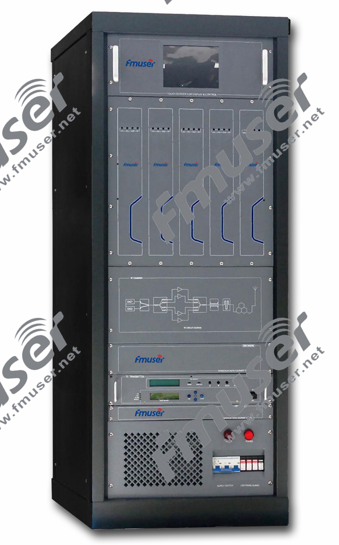
Broadcasting transmitters are the heart of radio and television stations, responsible for transmitting audio and video signals to a wide audience. They ensure the delivery of high-quality content over airwaves to radios and televisions in homes and vehicles. Broadcasting transmitters encompass various types, including FM broadcast transmitters, AM transmitters, and TV broadcast transmitters. Let's explore these types and their significance in the broadcasting industry.
- FM Broadcast Transmitters: FM (Frequency Modulation) broadcast transmitters are widely used for radio broadcasting. They transmit audio signals over the FM band, providing clear and high-fidelity sound to listeners. FM transmitters modulate the carrier frequency with the audio signal, allowing for a wide range of frequencies and stereo transmission. FM broadcasting is popular for its superior sound quality, making it suitable for music stations, talk shows, and other radio programming. >>Learn More
- AM Transmitters: AM (Amplitude Modulation) transmitters play a vital role in AM radio broadcasting. They modulate the amplitude of the carrier frequency with the audio signal to transmit voice and music. AM broadcasting has a long history and continues to be widely used for news, talk shows, sports, and other content. AM transmitters have a broad coverage area but are more susceptible to atmospheric interference, making them suitable for long-range transmissions and nighttime listening. >>Learn More
- TV Broadcast Transmitters: TV broadcast transmitters form the backbone of television broadcasting. They transmit audio and video signals over the air to televisions, enabling viewers to watch their favorite programs. TV transmitters use various modulation techniques, such as digital (ATSC) or analog (NTSC), depending on the broadcasting standards of a particular region. TV transmitters cover a wide frequency range and require higher power levels to reach the desired coverage area. >>Learn More
In addition to FM, AM, and TV broadcast transmitters, other types of broadcasting transmitters exist for specialized applications. These include digital radio transmitters (e.g., DAB, HD Radio), shortwave transmitters, and satellite uplink transmitters for broadcasting via satellites. These transmitters cater to specific broadcasting needs and technologies, offering expanded options for delivering content to diverse audiences.
Broadcasting transmitters are carefully designed, incorporating advanced technologies to ensure optimal signal quality, coverage, and compliance with regulatory standards. They are typically combined with antennas to radiate the signals into space for reception by radio or TV antennas.
FM Radio Transmitter
The FM radio transmitter plays a crucial role in capturing sound from the radio studio and broadcasting it through an FM antenna to the designated radio receiving area. This transmitter can either be a separate electronic device or a circuit within another electronic device. When the transmitter and receiver are combined in one unit, they are referred to as transceivers. In technical documentation, the term "transmitter" is often abbreviated as "XMTR" or "TX". The primary purpose of transmitters is to facilitate radio information communication over a specific distance.
How does FM Radio Transmitter work?
To transmit information, the transmitter receives electronic signals, such as audio (sound) signals from a microphone, video (TV) signals from a camera, or digital signals from a computer in the case of wireless network devices. The transmitter combines the information signal with a radio frequency signal to generate radio waves, known as the carrier signal. This process is referred to as modulation. Different types of transmitters use various methods to add information to the carrier signal. For instance, in AM transmitters, the information is added by altering the amplitude, while in FM transmitters, it is achieved by slightly changing the frequency. There are also numerous other modulation techniques utilized.
The radio signal generated by the transmitter is then directed to an antenna, which radiates the energy in the form of radio waves. The antenna can either be enclosed within the transmitter's housing or externally connected, as seen in portable devices like mobile phones, walkie-talkies, and garage door openers. In more powerful transmitters, the antenna is often located on the top of a building or a separate tower, connected to the transmitter via a feeder, or transmission line.
FM transmitters are categorized into low-power, medium-power, and high-power based on their output power capabilities. Each category serves different purposes and applications. Here's an overview of these FM transmitter categories:
- Low Power FM Transmitters: Low-power FM transmitters typically have an output power range of a few watts to tens of watts. They are commonly used in community radio stations, small-scale broadcasting, local events, and niche applications. These transmitters are compact in size and offer cost-effective solutions for limited coverage areas. Low-power FM transmitters are suitable for short-range broadcasts, such as within a neighborhood or a small campus.
- Medium Power FM Transmitters: Medium-power FM transmitters have higher output power capabilities, ranging from several tens to hundreds of watts. They are designed for regional radio stations and coverage areas requiring a moderate broadcast range. Medium-power transmitters offer improved signal strength and coverage compared to low-power transmitters, making them suitable for wider geographical regions. They are commonly utilized by regional broadcasters, educational institutions, and small to mid-sized radio stations.
- High Power FM Transmitters: High-power FM transmitters are built for commercial broadcasting and serve large coverage areas with a high number of listeners. They have significantly higher output power, ranging from several hundred watts to kilowatts or even multi-kilowatts. High-power transmitters are used by major radio stations and broadcasting networks to reach extensive geographical regions. These transmitters require more sophisticated infrastructure, larger antenna systems, and compliance with regulatory requirements for commercial broadcasting.
Output power is a critical factor in determining the coverage range and audience reach of an FM transmitter. The size, price, and specifications of FM transmitters vary within each power category, depending on the desired features and requirements of the specific application.
When selecting an FM transmitter, it is essential to consider the power category that best aligns with the intended coverage area, such as a small neighborhood or an entire region. Additionally, factors like regulatory restrictions, budget constraints, and the desired audio quality should be taken into account. Consulting with industry professionals and adhering to local broadcasting regulations will help in choosing the most suitable FM transmitter for a particular broadcasting application.
Recommended FM Transmitters for You
 |
 |
 |
| Low Power FM Transmitter Up to 100W | Medium Power FM Transmitter Up to 1000W | High Power FM Transmitter Up to 10kW |
Fixing Parts and Replacement Parts in FM Broadcast Transmitters
When a FM broadcast transmitter breaks down or malfunctions, it often requires certain components to be fixed or replaced. In the context of FM broadcast transmitters, "fixing parts" and "replacement parts" generally refer to the same thing, which are the components or modules that are used to repair or replace the faulty parts within the transmitter.
Fixing Parts
Fixing parts are the components used to remedy specific issues or faults in an FM broadcast transmitter. They are typically employed when the original part can be repaired, rather than completely replaced. Fixing parts may include items such as:
- Circuit board components: These can consist of capacitors, resistors, transistors, integrated circuits (ICs), diodes, and other electronic components. When any of these components fail or become damaged, they can be replaced individually, saving time and cost compared to replacing the entire circuit board.
- Connectors: Connectors are common points of failure in transmitter systems. They facilitate electrical connections between different components and cables. Faulty connectors may cause signal loss, intermittent connections, or other issues. Replacing these connectors can often resolve the problem.
- Power supply components: Transmitters rely on stable and reliable power sources. Fixing parts related to power supply components might include rectifiers, voltage regulators, fuses, and transformers. Replacing faulty power supply components can restore proper functionality to the transmitter.
Recommended High Power RF Transistors for You
 |
 |
 |
 |
| 150W MRFE6VP5150N | 300W MRFE6VP6300H | 600W MRFE6VP5600H | 1000W BLF188XR |
Replacement Parts
Replacement parts, on the other hand, are used when fixing the faulty component is not feasible or economically viable. In such cases, the entire part is substituted with a new one. Replacement parts can include:
- Power amplifiers: These are crucial components in FM broadcast transmitters, responsible for amplifying the signal to the desired power level. If a power amplifier fails, it often needs to be replaced entirely, as repairing it may be impractical or cost-prohibitive.
- Frequency synthesizers: Frequency synthesizers are used to generate the carrier frequency in FM broadcast transmitters. When a frequency synthesizer malfunctions, it typically requires a replacement rather than repair.
- Modulation or audio processing modules: These modules handle the modulation and audio processing functions in FM transmitters. When faulty, they may need to be replaced to restore proper audio quality and modulation performance.
Recommended High Power RF Transistors for You
 |
 |
 |
 |
| 200 Watts for FU-200A | 1000W for FU-1000D |
 |
 |
 |
| 1000W for FU-1000C | 150W for FMT5-150H |
AM Transmitters
AM transmitters generate AM signals, where the amplitude of the carrier wave is modulated to transmit audio or data information. These transmitters are commonly used in AM radio broadcasting, aircraft communications, and other applications that require long-range transmission of AM signals. >>Learn More

How do AM Transmitters Work?
AM transmitters typically consist of the following components:
- Carrier Oscillator: The carrier oscillator generates the carrier signal, which is typically a high-frequency sinusoidal waveform.
- Modulation Source: The modulation source provides the audio or data signal that is to be transmitted. This signal modulates the amplitude of the carrier wave.
- Modulator: The modulator combines the carrier signal with the modulation source. It modulates the carrier signal's amplitude in accordance with the audio or data signal, creating the AM signal.
- Power Amplifier: The power amplifier amplifies the modulated AM signal to a suitable power level for transmission.
- Antenna: The antenna is responsible for radiating the amplified AM signal into space for reception by the intended receivers.
The AM transmitter works by varying the amplitude of the carrier wave in accordance with the audio or data signal. This modulation process encodes the information onto the carrier signal, allowing it to be transmitted over long distances. At the receiving end, an AM receiver demodulates the received AM signal to recover the original audio or data signal.
Choosing AM Transmitters
Consider the following factors when choosing AM transmitters:
- Frequency Range: Determine the frequency range required for your AM transmission. Choose an AM transmitter that covers the specific frequency range of your application.
- Power Output: Evaluate the power output requirements of your transmission. Choose an AM transmitter that can provide the desired power level for your application, taking into account factors such as range and signal coverage.
- Modulation Capabilities: Consider the modulation capabilities of the AM transmitter. Determine whether it supports the modulation scheme required for your application, such as standard AM or variations like DSB (Double Sideband) or SSB (Single Sideband).
- Audio Quality: Assess the audio quality offered by the AM transmitter. Look for features such as low distortion, good signal-to-noise ratio, and adjustable audio gain to ensure clear and high-quality audio transmission.
- Reliability and Durability: Consider the reliability and durability of the AM transmitter. Look for a well-built, robust transmitter that can withstand the environmental conditions and provide consistent performance.
- Compliance and Standards: Verify that the AM transmitter complies with relevant industry standards and regulations in your region.
Recommended High Quality AM Transmitters for You
 |
 |
 |
 |
| 1KW AM Transmitter | 3KW AM Transmitter | 5KW AM Transmitter | 10KW AM Transmitter |
 |
 |
 |
 |
| 25KW AM Transmitter | 50KW AM Transmitter | 100KW AM Transmitter | 200KW AM Transmitter |
TV Transmitters
TV transmitters are electronic devices responsible for generating and transmitting television signals. They convert audio and video signals into electromagnetic waves that can be received by television antennas. TV transmitters are used in television broadcasting stations to transmit television programs to a wide audience.

How do TV Transmitters Work?
TV transmitters receive audio and video signals from a source, such as a television studio or satellite feed. The audio and video signals undergo modulation, where the information is encoded onto a carrier wave. The carrier wave is typically in the UHF (Ultra High Frequency) or VHF (Very High Frequency) frequency range, depending on the broadcasting standards used in a particular region.
Modulated audio and video signals are then amplified by the transmitter's power amplifier section to the desired power level for transmission. The amplified signals are fed into the transmission line, typically a coaxial cable or waveguide, which connects to the antenna. The antenna radiates the signal into space for reception by TV antennas in homes or other receiving devices.
TV transmitters must adhere to regulatory standards and broadcasting specifications set by the relevant authorities to ensure signal quality, coverage, and compliance with frequency allocations.
Choosing TV Transmitters
Consider the following factors when choosing TV transmitters:
- Frequency Range: Determine the frequency range required for TV transmission. Different regions and broadcasting standards may have specific frequency allocations for TV broadcasting. Choose a TV transmitter that covers the frequency range mandated by the regulatory authorities.
- Transmitter Power: Evaluate the power requirements for your TV transmission. Consider factors such as the coverage area, desired signal strength, and the type of terrain in the coverage area. Choose a transmitter with appropriate power output to meet your specific requirements.
- Frequency Agility: If your TV station needs to operate on multiple channels or frequency bands, consider a TV transmitter with frequency agility. Frequency-agile transmitters allow for flexibility in channel selection and can accommodate changes in frequency assignments or channel plans.
- Modulation Standards: Determine the modulation standards required for TV broadcasting in your region. Common modulation standards include ATSC (Advanced Television Systems Committee) for digital TV and NTSC (National Television System Committee) for analog TV. Choose a TV transmitter that supports the required modulation standard.
- Signal Quality and Reliability: Assess the signal quality and reliability offered by the TV transmitter. Consider features such as low distortion, high signal-to-noise ratio, and error correction capabilities for digital TV. Look for a reputable manufacturer known for reliable and high-quality transmitters.
- System Integration: Consider the compatibility and ease of integration with other components in your TV broadcasting system, such as audio/video sources, encoders, multiplexers, and transmission infrastructure.
Recommended TV Transmitters for You
 |
 |
 |
| CZH518A 3kW Analog TV Transmitter | FUTV3627 5W DVB Transmitter Amplifier | FU518D 100W Digital TV Transmitter |
Broadcast Antennas
FM Broadcast Antenna
An FM broadcast antenna is a specialized device used to radiate electromagnetic radio waves into the atmosphere. These antennas are designed to efficiently transmit FM radio signals, typically operating within the frequency range of 88 MHz to 108 MHz. They are crucial in broadcasting clear and reliable signals to a designated coverage area.
In the field of FM broadcasting, FM broadcast antennas are divided into transmit terminal antennas and receiving antennas.
At the receiving end, the antenna converts electrical signals into radio waves, while at the transmitting end, it performs the reverse process, converting radio wave signals back into electrical signals. The FM antenna and FM transmitter are essential components in various telecommunications applications.
In our daily lives, we frequently encounter wireless communication, such as radio stations where people can listen to radio programs using FM antennas. This is one of the significant applications of antennas in telecommunications. Since antennas form the foundation of wireless communication, they have numerous other daily applications, including TV signal transmission, satellite communications, remote sensing, and biomedical applications.
Antennas play a crucial role in enabling wireless communication and facilitating the transmission and reception of radio waves, making them indispensable in various fields and industries.
How does FM Broadcast Antenna work?
The antenna is an essential component of all radio equipment, typically used in conjunction with a transmitter or receiver. FM broadcast antennas operate based on the principles of electromagnetic radiation. They receive the radio frequency (RF) signal from the transmitter, which is then converted into electromagnetic waves. These waves are radiated into space, propagating outward in a specific pattern.
The key components of an FM broadcast antenna include:
- Radiating Element: This part of the antenna emits electromagnetic waves and can take the form of a vertical whip, a dipole, or an array of elements, depending on the design and requirements.
- Ground Plane: Many FM antennas incorporate a ground plane, which acts as a counterpoise to the radiating element. It enhances the antenna's performance and radiation pattern.
- Matching Network: FM broadcast antennas often require a matching network to ensure impedance compatibility between the transmitter and the antenna. This network optimizes power transfer and improves overall efficiency.
When transmitting signals, the antenna terminals receive the current provided by the radio transmitter, converting it into radio waves that are radiated into the atmosphere. At the receiving end, the antenna intercepts a portion of the power from the transmitter's antenna, generating current at the receiving terminal. This current is absorbed and converted by the receiver, allowing for the broadcasting of radio programs from the radio station.
Antennas can be designed for both transmitting and receiving radio waves equally (omnidirectional) or for specific directionality (directional or high-gain antennas). Additionally, FM broadcast antennas may include additional components such as paraboloid reflectors, horns, or parasitic elements, which help guide radio waves into desired radiation patterns or beams. If you aim to extend the range of radiation for these radio waves, a strong receiver is necessary.
Types of FM Broadcsat Antenna
FM broadcasting antennas can be categorized based on both their structure and power into the following types:
- Car FM Antenna: A car FM antenna is specially designed for vehicles to receive FM radio signals. It generally features a rod or whip-like element that is attached to the exterior of the vehicle. In some cases, car antennas may also include a suction pad, allowing them to securely attach to the windshield or other suitable surfaces inside the vehicle. These antennas are compact in size and specifically optimized for mobile FM reception, ensuring a clear and reliable radio signal while on the move. Car FM antennas play a crucial role in receiving FM radio signals while driving and are commonly found in automobiles to provide entertainment during travel. Their design and placement are carefully considered to meet the specific requirements of vehicular FM reception, ensuring an enjoyable listening experience while on the road.
- Vertical Whip Antenna (Low-Power): The vertical whip antenna, commonly utilized for low-power FM broadcasting applications, encompasses a vertical mast with a whip-like element positioned at its pinnacle. This type of antenna is typically employed in settings where power levels range from a few watts to a few hundred watts. The whip element, often crafted from metal, is strategically oriented in a vertical position to optimize the efficient radiation of FM signals.
- Dipole Antenna (Low to Medium Power): A dipole antenna comprises two identical conductive elements that extend either horizontally or vertically from a central feed point. The orientation of the dipole antenna can be adjusted based on the desired coverage pattern, whether it is horizontal or vertical. Dipole antennas find extensive use in FM broadcasting across a range of power levels, from low-power community radio stations to medium-power regional broadcasters. They offer versatility in terms of coverage and are well-suited for transmitting FM signals effectively.
- Yagi-Uda Antenna (Medium to High Power): The Yagi-Uda antenna, commonly known as a Yagi antenna, is a directional antenna featuring multiple elements arranged in a specific pattern. It includes one or more driven elements, a reflector, and one or more directors. Yagi antennas find widespread use in higher power FM broadcasting scenarios where precise directionality of coverage is desired, particularly by regional or national broadcasters. By focusing the transmitted signal in a specific direction, Yagi antennas enhance signal strength and reception quality for targeted areas.
- Log-Periodic Antenna (Medium to High Power): The log-periodic antenna is a broadband antenna that consists of a series of elements gradually increasing in length. It is designed to cover a wide frequency range while maintaining a relatively constant input impedance across that range. Log-periodic antennas are commonly employed in FM broadcasting, particularly for medium to high power levels and in applications requiring support for multiple channels or frequencies. The inherent broadband characteristics of log-periodic antennas make them well-suited for efficient transmission and reception of FM signals across a broad spectrum.
- Circularly Polarized Antenna (Low to High Power): Circularly polarized antennas are employed in FM broadcasting to enhance reception in areas with varying signal orientations. These antennas generate radio waves that oscillate in a circular pattern instead of a linear one, enabling improved reception regardless of the receiving antenna's polarization. Circularly polarized antennas find utility across a range of power levels, from low-power community stations to high-power commercial broadcasters. Their versatility and ability to mitigate the impact of polarization mismatches make them valuable for delivering consistent FM signals in diverse environments, ultimately improving overall reception quality.
How to Choose FM Broadcsat Antennas
Selecting the right FM broadcast antenna depends on several factors, including:
- Coverage Range: Determine the desired coverage area for your radio station. This will help you determine the antenna's power handling capability, gain, and radiation pattern required for adequate coverage.
- Frequency Range: Ensure that the antenna's operating frequency range matches the frequency band allocated for FM broadcasting (88 MHz to 108 MHz).
- Antenna Type: Consider various antenna designs such as vertical omnidirectional, directional, or circularly polarized antennas. Each type has its own advantages and considerations, depending on your specific requirements.
- Gain: Antennas with higher gain provide better signal strength in a specific direction. Consider the desired coverage area and the antenna's gain pattern to optimize signal distribution.
- Structural Considerations: Evaluate the available space, mounting options, and any physical limitations that may affect the antenna's installation.
Recommended FM Broadcast Antennas for You


Commercial AM Antennas
Commercial AM antennas are specialized antennas designed for professional broadcasting applications. They are typically used by radio stations and broadcasters to transmit AM signals over long distances. These antennas are carefully engineered to ensure efficient signal transmission and optimal coverage.
In the context of broadcasting, AM (Amplitude Modulation) refers to the modulation technique used for transmitting audio signals in the mediumwave frequency range. Therefore, AM broadcast antennas are designed to transmit and receive signals within the mediumwave frequency range. Hence, AM broadcast antennas can be considered a type of mediumwave antenna.
However, there can be other types of antennas that are designed to operate within the mediumwave frequency range. These antennas may not specifically be used for AM broadcasting purposes but can still receive or transmit signals in the mediumwave frequency spectrum. Some examples of other antennas that can be used in the mediumwave frequency range include: loop antennas, Beverage antennas, and wire antennas. These antennas are often utilized by radio enthusiasts, hobbyists, or individuals interested in improving their reception of mediumwave broadcasts. They are generally more accessible, affordable, and easier to set up compared to the complex and specialized antennas used in commercial broadcasting.
How They Work
Commercial AM antennas operate based on the principles of electromagnetic radiation and propagation. They are designed to efficiently radiate the electromagnetic waves generated by the broadcasting equipment, allowing them to propagate through the atmosphere and be received by radio receivers.
These antennas are typically tuned to specific frequencies used for AM broadcasting. They employ various design techniques to achieve high efficiency, gain, and directivity. Some commercial AM antennas use multiple elements, such as towers or arrays, to enhance signal strength and coverage.
Types of Commercial AM Antennas
Commercial AM antennas come in various types, each designed to meet specific broadcasting needs. Here are some common types of commercial AM antennas:
- Vertical Monopole Antennas: Vertical monopole antennas are widely used for commercial AM broadcasting. They consist of a tall vertical mast or tower with a conductive element extending from the top. The height of the antenna is carefully calculated to maximize signal efficiency and coverage. These antennas are omnidirectional, radiating the signal evenly in all directions.
- Directional Arrays: Directional arrays are composed of multiple antenna elements arranged in specific configurations. These antennas provide directional radiation patterns, allowing broadcasters to focus their signals in specific directions. Directional arrays are commonly used to target specific areas or minimize interference in congested broadcasting environments.
- T-Antennas: T-antennas, also known as T-type antennas or T-network antennas, are another type of commercial AM antenna. They comprise two vertical towers connected by a horizontal wire or top-loading structure. T-antennas offer enhanced signal efficiency and can provide good coverage for long-distance transmission.
- Folded Unipole Antennas: Folded unipole antennas, also called umbrella antennas, are a type of AM antenna that combines the benefits of a monopole antenna with a ground screen. They consist of a vertical mast connected to a horizontal top-loading structure, which is supported by a system of guy wires. Folded unipole antennas provide good radiation efficiency and coverage, making them suitable for various broadcasting applications.
- Log Periodic Antennas: Log periodic antennas, although more commonly used for other frequency ranges, can also be utilized for commercial AM broadcasting. These antennas have a wide frequency bandwidth and can provide relatively broad coverage. Log periodic antennas are often employed in situations where multiple frequencies need to be accommodated within a single installation.
- Shunt Fed Antenna: A shunt fed antenna is a type of AM antenna commonly used in commercial broadcasting. It features a unique feeding arrangement where the antenna mast is electrically connected to the ground through a section of transmission line or separate ground wire. This design allows for efficient transmission of AM signals, offers simplicity in installation, covers a wide bandwidth, and provides improved coverage in the horizontal plane. Proper grounding and tuning are essential for optimal operation.
Recommended AM Antennas for You
 |
 |
 |
 |
| Log Periodic Antenna | Omni-directional Receiving Antenna | Shunt Fed Antenna | Directional AM Antenna |
Commercial Shortwave Antennas
Commercial shortwave antennas are designed for professional broadcast applications in the shortwave frequency range. They are used by international broadcasters and large organizations to transmit signals over long distances. These antennas are specifically engineered to provide efficient and reliable long-range communication.
How They Work
Commercial shortwave antennas work on the principle of electromagnetic radiation and propagation. They are designed to efficiently radiate the electromagnetic waves generated by the broadcasting equipment, allowing them to propagate through the atmosphere and be received by radio receivers.
These antennas are typically designed to cover a wide frequency range and can transmit signals across multiple shortwave bands. They employ various techniques to achieve high power transmission, directivity, and gain to ensure effective long-distance communication.
Types of Commercial Shortwave Antennas
There are several types of commercial shortwave antennas used in professional broadcast applications. Some common types include:
- Curtain Arrays: Curtain arrays consist of multiple vertical wire elements suspended between towers or supports. These elements work together to create a directional radiation pattern, allowing for focused signal transmission in specific directions. Curtain arrays are known for their high power handling capabilities and are commonly used in international broadcasting.
- Log Periodic Antennas: Log periodic antennas are widely used in professional shortwave broadcasting. They have a distinctive design with a series of progressively larger elements, allowing for wide bandwidth coverage. Log periodic antennas provide good gain and directivity, making them suitable for multi-frequency transmission.
- Rhombic Antennas: Rhombic antennas are large, diamond-shaped wire antennas that are efficient for long-distance communication. They can handle high power levels and are commonly used in point-to-point broadcasting applications.
- Cage antennas: cage antennas, also known as cage monopole antennas or cage dipoles, are commonly used in radio frequency (RF) applications. They consist of a conductive cage structure that surrounds the radiating element, typically in the form of a cylindrical or box-like structure with evenly spaced wires or metal rods. This design enhances the antenna's radiation pattern, impedance characteristics, and reduces the impact of nearby objects and the ground plane. Additionally, the cage structure minimizes electromagnetic interference (EMI) from nearby electronics or metallic structures. These antennas are often utilized in scenarios where a balanced antenna system is necessary and can be fed with balanced transmission lines to reduce common mode noise.
- Quadrant antennas: Quadrant antennas, also known as quadrant monopole antennas or quadrant dipoles, are commonly used in RF applications. They consist of a radiating element divided into four quadrants, each fed with a separate signal for independent control of the radiation pattern. By adjusting the amplitudes and phases of these signals, the antenna's radiation pattern can be shaped to optimize performance in specific directions. Quadrant antennas are ideal for applications where directivity and beam steering are crucial, such as point-to-point communication systems or radar applications. Their design allows for flexible control of the radiation pattern, enabling beam shaping and steering without physically moving the antenna, making them suitable for rapid beam switching or tracking requirements.
Recommended Shortwave Antennas for You


Commercial TV Broadcast Antennas
A commercial TV broadcast antenna is a crucial component of a television broadcasting system. It is responsible for transmitting TV signals over the airwaves to reach a wide audience. TV antennas receive electrical signals containing audio and video information from the broadcasting station and convert them into electromagnetic waves that can be received and decoded by television sets.

How TV Broadcast Antennas Work
Commercial TV broadcast antennas work based on the principle of electromagnetic radiation. Here is a simplified explanation of how they function:
- Signal Reception: The antenna receives the electrical signals that are carrying the TV broadcast from the broadcasting station. These signals are transmitted through cables to the antenna.
- Signal Conversion: The received electrical signals are converted into electromagnetic waves that can propagate through the air. This conversion is accomplished by the antenna's design, which is optimized for efficient radiation and reception of electromagnetic waves.
- Signal Amplification: In some cases, the received signals may be weak due to various factors like distance from the broadcasting station or obstacles in the signal path. In such situations, the antenna may incorporate amplifiers or signal boosters to strengthen the signals.
- Signal Transmission: Once the electrical signals are converted into electromagnetic waves and amplified (if necessary), the antenna broadcasts these waves into the surrounding area. The antenna radiates the signals in a specific pattern to cover a designated geographic region.
- Frequency Selection: Different TV broadcasting services operate on different frequencies, such as VHF (Very High Frequency) or UHF (Ultra High Frequency). Commercial TV broadcast antennas are designed to operate within specific frequency ranges to match the broadcasting service they are intended for.
Choosing TV Station Antennas
Consider the following factors when choosing TV station antennas:
- Frequency Range: Determine the frequency range required for your TV broadcasting. Choose antennas that cover the specific VHF or UHF frequency range needed based on your broadcasting standards and regulations.
- Gain and Directivity: Evaluate the gain and directivity requirements for your coverage area. Higher gain and directivity provide greater signal strength and coverage distance. Consider factors such as the desired coverage area and terrain when selecting antenna types with suitable gain and directivity characteristics.
- Polarization: Determine the polarization required for your TV broadcasting system, such as horizontal or circular polarization. Choose antennas that offer the appropriate polarization for your specific application.
- Installation and Mounting: Consider the available space and mounting options for installing TV station antennas. Assess factors such as tower height, weight, wind loading, and compatibility with existing infrastructure during the selection process.
- Regulatory Compliance: Ensure that the chosen TV station antennas comply with relevant regulatory standards and broadcasting requirements in your region.
- System Integration: Consider the compatibility and ease of integration with other components in your TV broadcasting system, such as transmitters, transmission lines, and signal processing equipment.
There are several types of commercial TV broadcast antennas, each with its own advantages and applications. Here are some commonly used types:
Parabolic Dish Antennas
Parabolic dish antennas are commonly used in long-range TV broadcasting applications. These antennas feature a large curved reflector dish that focuses the transmitted or received signals onto a specific point, known as the focal point. Parabolic dish antennas are capable of achieving high gains and are frequently used for satellite TV broadcasting.
Log-Periodic Antennas
Log-periodic antennas are widely used in TV broadcasting due to their broadband characteristics, allowing them to operate across a wide range of frequencies in both the VHF and UHF bands. These antennas consist of dipole elements of varying lengths, strategically arranged to enable reception or transmission of signals over a broad frequency range. The design of log-periodic antennas ensures reliable performance across the entire TV broadcasting frequency spectrum. This versatility makes them ideal for scenarios where multiple channels or frequencies need to be accommodated without the need for multiple antennas. Log-periodic antennas are commonly utilized in TV broadcasting stations and as receiving antennas for consumers, offering efficient reception or transmission of TV signals across the entire frequency range, providing viewers with access to a wide range of channels without requiring antenna switching.
Yagi-Uda Antennas
Yagi-Uda antennas, commonly referred to as Yagi antennas, are popular directional antennas extensively used in TV broadcasting. These antennas feature multiple parallel elements, including a driven element, a reflector, and one or more directors. The unique design of Yagi-Uda antennas allows them to concentrate the transmitted or received signals in a specific direction, providing enhanced signal strength while minimizing interference. By precisely sizing and spacing the elements, Yagi-Uda antennas create a focused radiation pattern, increasing the gain and effectively directing the signal towards the desired target. These antennas are frequently deployed in TV broadcasting to achieve reliable long-range communication with minimal signal degradation or interference from unwanted sources.
Recommended UHF Yagi Antennas for You:
 |
| Max. 150W 14 dBi Yagi |
Panel Antennas
Panel antennas, also known as panel arrays or planar antennas, are commonly employed in TV broadcasting, particularly in urban areas. These antennas consist of multiple smaller antenna elements arranged in a planar configuration. By utilizing this arrangement, panel antennas provide increased gain and coverage over a specific area, making them well-suited for densely populated regions. Installed at elevated locations such as rooftops or towers, panel antennas offer a targeted coverage pattern, focusing transmitted or received signals in specific directions. This enables efficient signal distribution and improved signal quality, mitigating issues caused by obstacles like buildings. Panel antennas play a crucial role in urban TV broadcasting, where a large concentration of viewers necessitates reliable signal reception and distribution. Their design enhances the overall performance of the antenna system, ensuring that a larger number of viewers can receive high-quality TV signals without experiencing interference or signal loss.
Recommended TV Panel Antennas for You
VHF Panel types:
https://www.fmradiobroadcast.com/product/vhf-panel-antenna
 |
 |
 |
 |
| Band III Quadruple Dipole Panel | Band III Folded Dipole Panel | Band III Dual Dipole Panel | CH4 Band I Single Dipole Panel |
 |
 |
 |
| CH3 Band I Single Dipole Panel | CH2 Band I Single Dipole Panel | CH1 Band I Single Dipole Panel |
UHF Panel types:
https://www.fmradiobroadcast.com/product/uhf-panel-antenna
 |
 |
 |
| Dual-pol Slant Vertical Panel | UHF Vertical Dipole Panel | UHF Horizontal Dipole Panel |
Slot Antennas
Slot antennas are an alternative type of antenna used in TV broadcasting systems. They consist of a narrow slot cut into a conductive surface, such as a metal plate or waveguide, which acts as a radiating element, producing electromagnetic waves. Slot antennas are advantageous due to their compact size, low profile, and ability to provide a wide bandwidth. They are widely employed in modern TV broadcasting systems for their efficiency and easy integration with other components. In TV broadcasting, slot antennas are often utilized in large arrays or panels to enhance signal coverage. They can be designed for specific frequency bands, such as UHF, and arranged in an array to achieve desired gain and directional characteristics. Slot antennas are versatile, being efficient for both transmitting and receiving TV signals, making them well-suited for commercial TV broadcasting applications.
VHF Slot types:
https://www.fmradiobroadcast.com/product/vhf-slot-antenna
 |
| RDT014 Band III 4-Slot |
UHF Slot types:
https://www.fmradiobroadcast.com/product/uhf-panel-antenna
 |
 |
| 4-Slot Horizontal TV Slot | 8-Slot Horizontal TV Slot |
Omni-Directional Antennas
Omni-directional antennas are characterized by their ability to transmit or receive signals in all directions without any specific focus or directionality. They are designed to radiate or receive electromagnetic waves uniformly in a circular or spherical pattern around the antenna. In TV broadcasting, omni-directional antennas are particularly useful in scenarios where the broadcasting station wants to reach a broad audience spread across a wide area. These antennas are often installed at high elevations, such as on tall towers or rooftops, to maximize their coverage range. Omni-directional antennas typically have a vertically polarized design to align with the majority of TV broadcasts. They ensure that signals are transmitted or received evenly in all horizontal directions, allowing viewers to receive TV signals from any direction without the need to orient their antennas. By utilizing omni-directional antennas in commercial TV broadcasting, broadcasters can provide reliable signal coverage to viewers located in various directions around the transmitting site. This type of antenna is well-suited for urban areas, where TV signals may need to penetrate buildings or reach viewers located in different parts of a city.
Recommended UHF Onmidirectional for You
https://www.fmradiobroadcast.com/product/uhf-omnidirectional-antenna
 |
 |
 |
| 7/8" EIA Vertical, Max. 0.5/1kW | 7/8" or 1-5/8", Horizontal, Max. 1/1.5/2kW | 1-5/8", Vertical, Max. 1/2kW |
Wiring & Grounding
Antenna Mounting Kit:
An antenna mounting kit is a collection of equipment designed to securely install an antenna system in a specified location. It provides the necessary components to securely mount antennas or satellite dishes onto various surfaces or structures. The mounting kit ensures stability, optimal positioning, and efficient signal transmission for the antenna system.

List and Explanation:
- Mounting Brackets: These brackets are used to attach the antenna to a mounting surface. They provide stability and support for the antenna system.
- Mast or Pole: A mast or pole serves as the vertical support structure for the antenna. It provides elevation and positioning flexibility for optimal signal reception.
- Mounting Hardware: This includes nuts, bolts, screws, and washers required for securing the brackets and mast. These components ensure a secure and stable installation.
- Guy Wire Kit: In cases where additional support is needed, a guy wire kit may be included. It consists of wire, turnbuckles, and anchors used to stabilize the mast against wind or other external forces.
- Antenna Mounting Plate: A mounting plate is used to attach the antenna to the mounting brackets. It provides a stable connection and ensures proper alignment.
How the Equipment Works Together as the Antenna Mounting System:
The antenna mounting kit's components work collectively to create a stable and properly aligned antenna system. The mounting brackets secure the antenna to the chosen surface, ensuring a strong and secure attachment. The mast or pole provides the necessary elevation and positioning to optimize signal reception. The mounting hardware, including nuts, bolts, screws, and washers, ensures a secure and reliable connection between the brackets, mast, and mounting surface. In cases where additional stability is required, the guy wire kit can be used to anchor the mast and prevent swaying or movement caused by external forces. The antenna mounting plate facilitates the attachment of the antenna to the mounting brackets, providing a secure and aligned installation.
Step-by-Step Mounting Process for a Broadcast Antenna System:
- Select a suitable location for the antenna system, considering factors such as line of sight, elevation, and structural integrity of the mounting surface.
- Attach the mounting brackets to the chosen mounting surface using the appropriate mounting hardware.
- Attach the mast or pole to the mounting brackets using the provided hardware, ensuring a secure and plumb installation.
- Connect the antenna to the mounting plate using the provided hardware, aligning it properly for optimal signal reception.
- Securely fasten the antenna to the mounting plate using the provided hardware.
- If necessary, install the guy wire kit by anchoring the wires to the ground or nearby structures and tensioning them appropriately to provide additional stability to the mast.
- Perform a final inspection to ensure all connections are secure, the antenna is properly aligned, and the mounting system is stable.
- Check for any obstructions or potential interference that may impact the antenna's performance.
Grounding Kit Components:
Grounding kit components are essential elements used in electrical systems to establish a safe and effective grounding connection. These components are designed to protect equipment from electrical surges, minimize interference, and ensure proper signal transmission.

Explanation of Grounding Components:
- Grounding Rod: A grounding rod is a metal rod inserted into the ground near the antenna system. It establishes a direct connection with the earth, allowing electrical surges to dissipate safely.
- Grounding Wire: A conductive wire connects the grounding rod to the grounding kit components. It provides a low-resistance path for electrical currents to flow, ensuring effective grounding.
- Grounding Clamps: These clamps are included in the grounding kit to securely attach the grounding wire to various components, such as the antenna mast or equipment enclosure. They establish a reliable electrical connection.
- Grounding Plate: The grounding plate, if included in the kit, is connected to the grounding wire. It offers a larger surface area for improved grounding performance and is often placed in an area with good soil conductivity.
- Grounding Busbar: If part of the grounding kit, the grounding busbar acts as a central point for grounding connections. It is a conductive strip or bar that connects multiple grounding wires or components.
- Grounding Lug: The grounding lug, found in the grounding kit, connects the grounding wire to the grounding busbar or plate. It ensures a secure and low-resistance connection.
How the Components Work Together as a Grounding System:
In a grounding system for a broadcast antenna, the various components collaborate to create a safe and effective grounding setup. The grounding rod establishes a direct connection to the earth, while the grounding wire connects it to the grounding components in the kit. The grounding clamps securely attach the grounding wire to the antenna mast or equipment enclosure. If present, the grounding plate enhances grounding performance by providing a larger surface area. The grounding busbar acts as a centralized point, connecting multiple grounding wires or components. The grounding lug enables the connection between the grounding wire and the central grounding point, ensuring a reliable and low-resistance link.
Step-by-Step Grounding Process for a Broadcast Antenna System:
- Identify a suitable location near the antenna system to install the grounding rod.
- Dig a hole deep enough to accommodate the grounding rod, ensuring it is firmly placed in the ground.
- Connect one end of the grounding wire to the grounding rod using appropriate clamps.
- Route the grounding wire from the grounding rod to the antenna mast or equipment enclosure, securing it with grounding clamps along the way.
- If included in the kit, attach the grounding plate to the grounding wire and position it in an area with good soil conductivity.
- Connect the grounding wire to the grounding busbar using the grounding lug, creating a centralized grounding point.
- Ensure all connections are secure and free of any corrosion or loose fittings.
- Perform regular inspections and maintenance of the grounding system to ensure its effectiveness.
Rigid Coaxial Transmission Lines
Rigid coaxial transmission lines are specifically engineered for high-power RF applications, offering superior electrical performance and mechanical stability. These transmission lines feature a rigid outer conductor, ensuring efficient signal propagation and minimizing signal loss. They serve as a critical component in the transmission chain, connecting the transmitter to the associated cables.

Similar to how optical cables transmit signals through optical fibers, rigid transmission lines are utilized for high-frequency signal transmission. Within these lines, electromagnetic waves propagate back and forth between the core line and feeder, while the shielding layer effectively blocks external interference signals. This shielding capability ensures the integrity of the transmitted signals and reduces the loss of useful signals through radiation.
These transmission lines are commonly used in applications that require high-power handling and low signal loss, such as broadcast systems, cellular networks, and high-frequency communication systems. Some common sizes of rigid coaxial transmission lines include:
- 7/8" Rigid Coaxial Transmission Line
- 1-5/8" Rigid Coaxial Transmission Line
- 3-1/8" Rigid Coaxial Transmission Line
- 4-1/16" Rigid Coaxial Transmission Line
- 6-1/8" Rigid Coaxial Transmission Line
High Quality Rigid Lines In Stock:
https://www.fmradiobroadcast.com/product/detail/rigid-coaxial-transmission-line.html
How Rigid Coaxial Transmission Lines Work
Rigid coaxial transmission lines work on the same principle as other coaxial cables. They consist of a central conductor, a dielectric insulator, an outer conductor, and an outer jacket. The inner conductor carries the RF signal, while the outer conductor provides shielding against external interference.
The rigid outer conductor of these transmission lines ensures minimal signal leakage and reduces signal loss. It also provides mechanical stability, allowing the transmission lines to maintain their shape and performance even under high-power conditions.
Choosing Rigid Coaxial Transmission Lines
Consider the following factors when choosing rigid coaxial transmission lines:
- Power Handling Capacity: Determine the power handling requirements of your RF application. Choose a rigid coaxial transmission line that can handle the power levels required without significant signal loss or degradation.
- Signal Loss: Evaluate the signal loss characteristics of the transmission line at your desired frequency range. Lower signal loss ensures better signal integrity over longer distances.
- Environmental Considerations: Assess the environmental conditions the transmission line will be exposed to, such as temperature, moisture, and UV resistance. Ensure that the chosen transmission line is suitable for the specific environmental requirements of your application.
- Frequency Range: Verify that the transmission line supports the frequency range required for your application. Different rigid coaxial transmission lines are designed for specific frequency ranges, so choose one that matches your frequency needs.
- Compatibility: Ensure that the transmission line is compatible with your RF system's connectors and other components. Verify that the connectors and terminations for the chosen transmission line are readily available and suitable for your specific application.
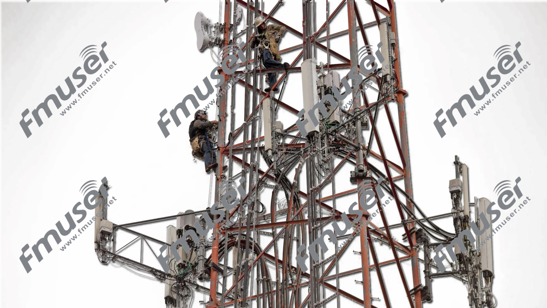
Tower or Mast
A tower or mast is a freestanding structure designed to securely accommodate antennas and associated equipment. It provides the necessary height and stability required for optimal antenna performance. Towers are commonly made of steel or aluminum, ensuring durability and resistance to environmental elements.
How it works?
The primary function of a tower or mast is to elevate antennas to a strategic height that facilitates signal propagation over long distances and wider areas. By positioning the antennas at an elevated location, they can overcome obstructions and minimize signal blockage, resulting in enhanced coverage and improved signal quality.
Towers or masts are engineered to withstand wind loads, seismic forces, and other environmental factors that may impact the stability of the antenna system. They are designed to be structurally sound, ensuring the safety of personnel working on or near the tower.
Differences for AM, FM, and TV Stations
While towers or masts serve as support structures for antenna systems across various applications, there are notable differences in their design and requirements for AM, FM, and TV stations. These differences primarily stem from the specific characteristics of the signals and the coverage needs of each broadcasting format.
- AM Station Towers or Masts: AM radio stations typically require taller and more robust towers due to the long wavelengths of AM signals. These signals tend to propagate along the ground, requiring towers with heights that allow for wider coverage and overcome obstacles. AM station towers are usually grounded and can incorporate a system of guy wires to provide additional stability against lateral forces.
- FM Station Towers or Masts: FM radio signals have shorter wavelengths compared to AM signals, allowing them to propagate in a more direct line-of-sight manner. As a result, FM station towers can be shorter in height compared to AM towers. The focus for FM towers is to position antennas at an optimal elevation to achieve line-of-sight transmission, minimizing obstructions and maximizing signal coverage.
- TV Station Towers or Masts: TV stations require towers or masts to support antennas that transmit a wide range of frequencies for different TV channels. These towers tend to be taller than FM towers to accommodate the higher frequencies used in TV broadcasting. TV station towers often incorporate multiple antennas and are engineered to provide directional radiation patterns, allowing for targeted coverage in specific areas.
Structural Considerations and Regulations
Regardless of the broadcasting format, the structural integrity and compliance with regulations remain critical for tower or mast installations. Factors such as wind load, weight distribution, ice loading, and seismic considerations must be addressed to ensure the safety and stability of the structure under various environmental conditions.
Moreover, each country or region may have specific regulations and guidelines governing tower or mast installations, including requirements for lighting, painting, and aviation safety.
Here's a comparison table highlighting the key differences between the towers or masts used in AM, FM, and TV stations:
| Aspect | AM Station Towers/Masts | FM Station Towers/Masts | TV Station Towers/Masts |
|---|---|---|---|
| Height Requirement | Taller due to longer wavelengths of AM signals | Relatively shorter than AM towers for line-of-sight propagation | Taller than FM towers to accommodate higher TV broadcasting frequencies |
| Signal Propagation | Ground-wave propagation with wider coverage | Line-of-sight propagation with a focus on direct transmission | Line-of-sight transmission with targeted coverage in specific areas |
| Structural Consideration | Require robust construction and grounding, may incorporate guy wires | Sturdy design for elevation and line-of-sight propagation | Sturdy design to accommodate multiple antennas and directional radiation patterns |
| Regulatory Compliance | Compliance with regulations governing tower height and grounding | Compliance with regulations for tower height and line-of-sight | Compliance with regulations for tower height, multiple antennas, and directional radiation patterns |
| Professional Consultation | Important for compliance, safety, and optimization | Important for compliance, safety, and optimal line-of-sight coverage | Important for compliance, safety, and optimal coverage for multiple TV channels |
Choosing the Right Tower or Mast
When choosing a tower or mast for an antenna system, several factors need to be considered:
- Height Requirements: Determine the required height based on the desired coverage area and the specific characteristics of the RF signals being transmitted or received.
- Load Capacity: Consider the weight and size of the antennas and associated equipment to ensure that the tower or mast can safely support the intended load.
- Environmental Conditions: Evaluate the environmental conditions at the installation site, including wind speeds, temperature variations, and the potential for ice or snow accumulation. Choose a tower or mast that is designed to withstand these conditions.
- Regulatory Compliance: Compliance with local regulations and building codes is crucial for safety and legal reasons. Ensure that the chosen tower or mast meets all applicable standards and requirements.
- Future Expansion: Anticipate future growth or changes in the antenna system and select a tower or mast that can accommodate additional antennas or equipment if needed.
Why FM Transmitting Tower is important?
The tower will either act as an antenna itself or support one or more antennas on its structure because they have to send powerful signals over long distances, including microwave dishes. These antennas emit radiofrequency (RF) electromagnetic energy (EME). But you don't need anything that big on your TV or radio at home: a much smaller antenna will do the job fine.
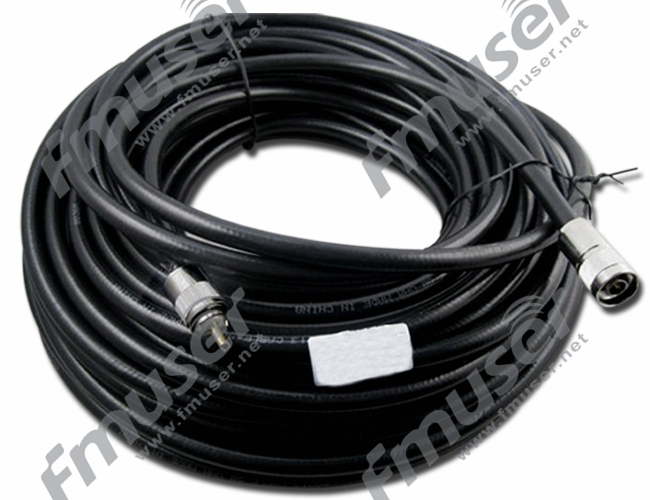
RF Coaxial Cable
RF coaxial cables are essential components in the transmission of high-frequency signals. They are constructed with several key elements: a central conductor, dielectric insulation, shielding, and an outer jacket. This design enables effective signal transmission while minimizing signal loss and external interference.

How do RF Coaxial Cables Work?
RF coaxial cables work by transmitting high-frequency signals along the central conductor while the shielding prevents signal leaks and external interference. The central conductor, typically made of solid or braided copper wire, carries the electrical signal. It is surrounded by a layer of dielectric insulation, which serves to maintain the integrity and stability of the signal by preventing signal leakage or interference.
To further protect the signal from external interference, coaxial cables incorporate shielding. The shielding layer surrounds the dielectric insulation, acting as a barrier against electromagnetic interference (EMI) and radio frequency interference (RFI). This shielding prevents unwanted noise or signals from degrading the transmitted signal.
The outer jacket provides additional protection and insulation to the internal components of the coaxial cable, safeguarding it from physical damage and environmental factors.
The coaxial design, with its central conductor surrounded by shielding, offers distinct advantages over other cable types. This configuration provides superior signal integrity, ensuring that the transmitted signal remains robust and accurate. Additionally, the shielding effectively blocks external noise, resulting in clearer and more reliable signal transmission.
Types of Coaxial Cable
Coaxial cables come in various types, each designed for specific applications and frequency ranges. Here's an overview of some commonly used types of coaxial cables:
- RG178R: G178 is a flexible coaxial cable with a small diameter, commonly used in high-frequency applications where space is limited. It is lightweight, has good flexibility, and is suitable for applications such as mobile communications, aerospace, and military equipment.
- SYV-50: SYV-50 is a 50-ohm coaxial cable often used for video transmission and lower frequency RF applications. It is commonly found in CCTV systems, video surveillance, and other applications where a lower impedance is required.
- RG58: RG58 is a popular 50-ohm coaxial cable suitable for a wide range of RF applications. It offers good flexibility, moderate power handling capacity, and is commonly used in telecommunications, radio communication, and general-purpose RF connections.
- RG59: RG59 is a 75-ohm coaxial cable primarily used for video and TV signal transmission. It is commonly employed in cable and satellite television systems, CCTV installations, and video applications where impedance matching to 75 ohms is necessary.
- RG213: RG213 is a thick, low-loss coaxial cable with a larger diameter and higher power handling capacity. It is suitable for high-power RF applications and is commonly used in broadcast systems, amateur radio, and long-range communication.
Other Types
There are numerous other types of coaxial cables available, each designed for specific applications and frequency ranges. Some additional examples include:
- RG6: A 75-ohm coaxial cable commonly used for cable TV, satellite TV, and broadband internet applications.
- LMR-400: A low-loss coaxial cable suitable for high-power and long-distance RF applications. It is commonly used in outdoor installations and wireless communication systems.
- Triaxial Cable: A specialized coaxial cable with an additional layer of shielding, providing enhanced protection against electromagnetic interference (EMI) and noise.
These are just a few examples of the many coaxial cable types available, each with its own specific characteristics and applications. When selecting a coaxial cable, consider the requirements of your application, including the desired frequency range, impedance, power handling capacity, and environmental conditions.
Choosing RF Coaxial Cables
Consider the following factors when choosing RF coaxial cables:
- Frequency Range: Determine the frequency range of your application. Different coaxial cables are designed to operaste within specific frequency ranges. Choose a cable that can handle your desired frequency range without significant signal loss.
- Impedance: Match the impedance of the coaxial cable to your system requirements. Common impedance values for RF coaxial cables are 50 ohms and 75 ohms, with 50 ohms being the most commonly used in RF applications.
- Signal Loss and Attenuation: Evaluate the cable's attenuation characteristics at the desired frequency range. Lower signal loss ensures better signal integrity and transmission efficiency.
- Power Handling Capacity: Verify that the cable can handle the power levels required for your application. Higher power levels may require cables with larger conductors and better power handling capabilities.
- Cable Type and Standards: Different cable types are available with specific characteristics. There are numerous other types of RF coaxial cables available, each with specific characteristics and applications. Examples include RG58, RG59, RG213, and many more, each designed for different frequency ranges, power handling capacities, and applications.
- Environmental Considerations: Assess the environmental conditions the cable will be exposed to. Consider factors such as temperature range, moisture resistance, UV resistance, and flexibility requirements.
Recommended RF Coxial Cables for You
 |
 |
| SYV-50 Series (8/15/20/30M) | RG178 1/3/5/10M B/U PTFE FTP |
Hardline Coax
Hardline coax is a type of coaxial cable that features a rigid outer conductor, typically made of copper or aluminum. Unlike flexible coax cables, hardline coax maintains its shape and cannot be easily bent or flexed. It is designed for applications that demand higher power handling capacity, lower signal loss, and better shielding.

How does Hardline Coax Work?
Hardline coax works on the same principle as other coaxial cables. It consists of a central conductor surrounded by a dielectric insulator, which is further surrounded by the rigid outer conductor. This design ensures minimal signal loss and provides excellent shielding against external interference.
The rigid outer conductor of hardline coax offers superior electrical performance and mechanical stability. It minimizes signal leakage and reduces attenuation, making it suitable for high-power RF transmission over longer distances.
Types of Hardline Coax
Hardline coaxial cables come in various sizes, each designed for specific power handling capacities and applications. Here's an overview of some commonly used types of hardline coax:
- 1-5/8" Hardline Coax: 1-5/8" hardline coax is a large-sized hardline coaxial cable commonly used in high-power RF applications. It offers high power handling capacity and low signal loss, making it ideal for long-range and high-power transmission requirements. It is frequently utilized in applications such as broadcast transmission, cellular base stations, and high-frequency communication systems.
- 1/2" Hardline Coax: 1/2" hardline coax is a medium-sized hardline coaxial cable widely used in various RF applications. It provides good power handling capacity and moderate signal loss. 1/2" hardline coax is suitable for indoor and outdoor installations and finds applications in wireless communication, amateur radio, and small cell systems.
- 7/8" Hardline Coax: 7/8" hardline coax is a popular size used in many RF applications where a balance between power handling and cable size is required. It is commonly deployed in cellular networks, microwave links, and other high-frequency communication systems. 7/8" hardline coax offers a good compromise between power handling capacity, signal loss, and ease of installation.
- 3/8" Hardline Coax: Smaller-sized hardline coax suitable for short-range communication systems, such as Wi-Fi networks and small wireless devices.
- 1-1/4" Hardline Coax: Larger-sized hardline coax used in high-power industrial applications and long-range wireless communication systems.
- 2-1/4" Hardline Coax: Very large-sized hardline coax deployed in high-power, long-distance communication systems, including broadcast towers and large-scale wireless networks.
Choosing Hardline Coax
Consider the following factors when choosing hardline coax:
- Power Handling Capacity: Determine the power handling requirements of your RF application. Choose a hardline coax that can handle the power levels required without significant signal loss or degradation.
- Signal Loss: Evaluate the signal loss characteristics of the hardline coax at your desired frequency range. Lower signal loss ensures better transmission efficiency and signal integrity over longer distances.
- Environmental Considerations: Assess the environmental conditions the hardline coax will be exposed to, such as temperature, moisture, and UV resistance. Ensure that the chosen hardline coax is suitable for the specific environmental requirements of your application.
- Installation Requirements: Consider the ease of installation and any specific installation requirements. Hardline coax cables have a rigid structure that may require careful handling and appropriate connectors for termination.
- Frequency Range: Verify that the hardline coax supports the frequency range required for your application. Different hardline coax types are designed for specific frequency ranges, so choose one that matches your frequency needs.
- Compatibility: Ensure that the hardline coax is compatible with your RF system's connectors and other components. Verify that the connectors and terminations for the chosen hardline coax are readily available and suitable for your specific application.
Recommended Hardline Coax Cables for You
 |
 |
 |
| 1/2" Hardline Feeder | 7/8" Hardline Feeder | 1-5/8" Hardline Feeder |
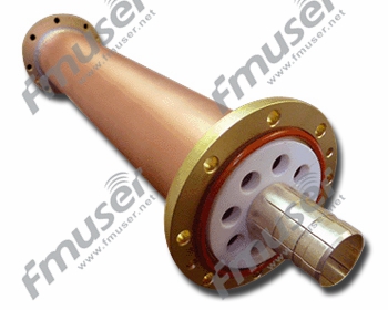
Parts of Rigid Coaxial Transmission Lines
Rigid coaxial transmission lines consist of various parts that work together to provide efficient signal transmission and support.

Here's an introduction to common parts of rigid coaxial transmission lines:
- Rigid Line Tube: The main section of the transmission line, consisting of a rigid outer conductor, inner conductor, and dielectric insulator. It provides the path for the RF signal transmission.
- Matching Sections: Used to ensure proper impedance matching between different sections of the transmission line or between the transmission line and other system components.
- Inner Support: Support structure that holds the inner conductor in place and maintains proper spacing between the inner and outer conductors.
- Flange Support: Provides support and alignment for flange connections, ensuring proper mating and electrical contact.
- Flange to Unflanged Adapter: Converts a flanged connection to an unflanged connection, allowing for compatibility between different components or sections of the transmission line.
- Outer Sleeve: Surrounds and protects the outer conductor of the transmission line, providing mechanical stability and shielding.
- Inner Bullet: Ensures proper alignment and electrical contact between the inner conductor and other components.
- Elbows: Used to change the direction of the transmission line, allowing for installation in tight spaces or routing around obstacles.
- Coaxial Adaptors: Used for connection or conversion between different types of coaxial connectors.
When choosing rigid coaxial transmission lines and their associated parts, consider the specific requirements of your RF system, power handling capacity, frequency range, environmental conditions, and compatibility with other components.
Recommended Parts & Components of Rigid Lines for You
 |
 |
 |
 |
| Rigid Coaxial Transmission Line Tubes | 90 Degree Elbows | Flange Inner Supports | Flanged to Unflanged Adaptor |
 |
 |
 |
 |
| Inner Bullet | Inner Support | Matching Sections | Outer Sleeves |
 |
|||
| Coaxial Adaptors |
|||
Coax Connectors
Coax connectors are designed to ensure proper electrical continuity and impedance matching between coaxial cables and the devices they connect to. They have a characteristic design that allows for easy and reliable connection and disconnection, while maintaining the integrity of the signal transmission within the coaxial cable.

How do Coax Connectors Work?
Coax connectors typically consist of a male and a female connector. The male connector has a center pin that extends into the female connector, creating a secure connection. The outer conductors of both connectors are threaded or feature some form of locking mechanism to ensure proper coupling and to prevent accidental disconnection.
When two coax connectors are mated together, the center conductors make contact, allowing the signal to pass through. The outer conductors (shields) of the connectors maintain electrical continuity and provide shielding against external interference, ensuring proper signal transmission and minimizing signal loss.
Types of Coax Connectors
Coax connectors come in various types, each designed for specific applications and frequency ranges. Here's an overview of some commonly used types of coax connectors:
- RF Coaxial Adaptor: An RF coaxial adaptor is not a specific type of connector but a device used to connect or convert between different types of coaxial connectors. Adaptors allow for seamless connectivity between various coaxial cable types or connectors when compatibility issues arise.
- N-Type Coaxial Connector: The N-type coaxial connector is a threaded connector widely used in RF applications up to 11 GHz. It offers a reliable connection, good performance, and is capable of handling moderate power levels. The N-type connector is commonly used in wireless communication systems, broadcast equipment, and test and measurement applications.
- 7/16 DIN (L-29) Coaxial Connector: The 7/16 DIN or L-29 coaxial connector is a larger, high-power connector suitable for high-frequency applications. It provides low loss and high power handling capabilities, making it ideal for cellular base stations, broadcast systems, and high-power RF applications.
- EIA Flange Coaxial Connector: The EIA (Electronic Industries Alliance) flange coaxial connector is used for high-power RF connections. It features a circular flange with bolt holes for secure mounting and is commonly found in waveguide systems, which are used for high-frequency and microwave transmission.
- BNC (Bayonet Neill-Concelman): A bayonet-style connector commonly used in audio and video applications up to 4 GHz.
- SMA (SubMiniature version A): A threaded connector used for frequencies up to 18 GHz, often found in wireless and microwave systems.
- TNC (Threaded Neill-Concelman): A threaded connector similar to BNC but with improved performance at higher frequencies.
Choosing Coax Connectors
Consider the following factors when choosing coax connectors:
- Frequency Range: Consider the frequency range of the coaxial cable and equipment you are connecting. Ensure that the chosen coax connector is designed to handle the frequency range without significant signal degradation.
- Impedance Matching: Verify that the coax connector matches the impedance specification of the coaxial cable (typically 50 or 75 ohms). Proper impedance matching is crucial for minimizing signal reflections and maintaining signal integrity.
- Environmental Considerations: Assess the environmental conditions of the intended application. Some connectors may offer better sealing or weatherproofing features, making them suitable for outdoor or harsh environments.
- Durability and Reliability: Consider the durability and reliability of the coax connector. Look for connectors constructed with high-quality materials, precision manufacturing, and reliable locking mechanisms to ensure a secure and long-lasting connection.
- Compatibility: Ensure that the chosen coax connector is compatible with the coaxial cable type and the devices or equipment you are connecting. Verify the connector's dimensions, threading, and interface to ensure proper mating and secure connections.


LPS Lightning Protection System
An LPS, or Lightning Protection System, is a comprehensive system of measures and devices implemented to mitigate the destructive impact of lightning strikes.

It aims to offer a conductive path for the lightning current to safely dissipate into the ground, preventing damage to structures and sensitive equipment.
How does an LPS work?
An LPS typically consists of the following components:
- Air Terminals (Lightning Rods): Installed at the highest points of a structure, air terminals attract the lightning strike and provide a preferred path for the discharge.
- Down Conductors: Metallic conductors, usually in the form of rods or cables, connect the air terminals to the ground. They conduct the lightning current to the ground, bypassing the structure and equipment.
- Grounding System: A network of conductive elements, including ground rods or plates, facilitates the dissipation of the lightning current into the ground.
- Surge Protection Devices (SPDs): SPDs are installed at strategic points within the electrical and electronic systems to divert transient electrical surges caused by lightning strikes away from sensitive equipment. They help prevent damage to equipment due to overvoltage.
By providing a path of least resistance for the lightning current, an LPS ensures that the energy from a lightning strike is safely channeled away from the structure and its equipment, reducing the risk of fire, structural damage, and equipment failure.
Choosing an LPS
Consider the following factors when choosing an LPS:
- Risk Assessment: Conduct a risk assessment to determine the level of lightning exposure to the structure and equipment. Factors such as location, local weather patterns, and building height influence the risk. Higher-risk areas may require more comprehensive protection measures.
- Compliance with Standards: Ensure that the LPS meets the requirements of recognized standards such as NFPA 780, IEC 62305, or the relevant local building codes. Compliance with these standards ensures that the LPS is designed and installed appropriately.
- Structural Considerations: Consider the structural characteristics of the building or facility. Factors such as height, roof type, and material composition influence the design and installation of air terminals and down conductors.
- Equipment Protection: Assess the equipment that requires protection from lightning-induced surges. Different equipment may have specific surge protection requirements. Consult with experts to determine the appropriate placement and specifications of SPDs to safeguard critical equipment.
- Maintenance and Inspection: Ensure that the LPS is regularly inspected and maintained. Lightning protection systems can degrade over time, and regular maintenance helps to identify and address any issues or faulty components.
- Certification and Expertise: Engage certified lightning protection professionals or consultants with expertise in designing and installing LPSs. They can provide guidance and ensure that the system is correctly implemented.
Recommended Light Protection System for You
|
More Details:
https://www.fmradiobroadcast.com/product/detail/lps-lightning-protection-system.html |
Items | Specifications |
| Material (lightning rod) | Copper and stainless steel | |
| Material (insulation rod) | Epoxy resin | |
| Material (grounding rod) | iron-made with electroplated surface | |
| Style | Optional from single-needle style, solid tip spherical style, multi-ball style, etc. | |
| Size (cm) | 1.6M |

Studio to Transmitter Link
Studio to Transmitter Link Equipment
A Studio to Transmitter Link (STL) is a dedicated point-to-point communication system that connects a radio station's studio or production facility to its transmitter site. The purpose of an STL is to transmit the audio signal from the studio or production facility to the transmitter, ensuring reliable and high-quality transmission of the radio programming.

How does a Studio to Transmitter Link Work?
STLs typically utilize a combination of wired or wireless transmission methods to establish a reliable link between the studio and transmitter site. The specifics of the STL setup can vary depending on the distance between the studio and the transmitter, geographical considerations, available infrastructure, and regulatory requirements. Here are a few common types of STL systems:
- Microwave Links: Microwave STLs use high-frequency radio waves to establish a line-of-sight connection between the studio and transmitter site. They require clear visibility between the two locations and utilize microwave antennas to transmit and receive the signals.
- Satellite Links: Satellite STLs utilize satellite communication to establish a link between the studio and the transmitter site. They involve the use of satellite dishes and require a satellite uplink at the studio and a downlink at the transmitter site.
- IP Networks: IP-based STLs leverage internet protocol (IP) networks, such as Ethernet or internet connections, to transmit audio and data between the studio and transmitter site. This method often involves encoding the audio signal into IP packets and then transmitting them over the network infrastructure.
STL systems can also incorporate redundancy mechanisms to ensure reliability. This may include the use of backup connections or redundant equipment to minimize the risk of signal loss or disruption.
Choosing a Studio to Transmitter Link
Consider the following factors when choosing a Studio to Transmitter Link:
- Distance and Line of Sight: Determine the distance between the studio and the transmitter site and assess whether there is a clear line of sight or suitable infrastructure available for the STL setup. This will help determine the appropriate technology, such as microwave or satellite, based on the specific requirements of the transmission path.
- Reliability and Redundancy: Evaluate the reliability and redundancy options provided by the STL system. Look for features like backup connections, equipment redundancy, or failover mechanisms to ensure uninterrupted transmission in case of link or equipment failures.
- Audio Quality and Bandwidth: Consider the audio quality requirements of your radio station. Ensure that the STL system can handle the necessary bandwidth to transmit the audio signal without degradation or loss of quality.
- Regulatory Compliance: Understand and comply with any regulatory requirements related to frequency allocation, licensing, or other legal aspects that may impact the choice and implementation of the STL system.
- Scalability and Future Expansion: Assess the scalability of the STL system to accommodate potential future growth or changes in the radio station's needs. Consider the ability to upgrade or expand the system easily as required.
Recommened Studio to Transmitter Link Solutions for You:
 |
 |
 |
 |
| 5.8 GHz 10KM1 HDMI/SDI | 5.8 GHz 10KM 4 AES/EBU | 5.8 GHz 10KM 4 AV/CVBS |
 |
 |
 |
| 5.8 GHz 10KM 4 HDMI/Stereo | 5.8 GHz 10KM 8 HDMI | 100-1K MHz & 7-9 GHz, 60KM, Low-cost |
STL Transmitter
STL (Studio-to-Transmitter Link) transmitters are devices specifically designed for broadcasting applications. Their purpose is to establish a reliable and high-quality audio or video link between the studio and the transmitter site of a radio or TV station. These transmitters provide a dedicated and dependable connection, ensuring that the broadcasted signals reach the transmitter without degradation or interference. By transporting audio or video signals in real-time, STL transmitters play a crucial role in maintaining the integrity and quality of the content being transmitted. When choosing an STL transmitter, factors such as reliability, signal quality, and compatibility with existing equipment should be carefully considered.
How do STL Transmitters Work?
STL transmitters typically operate in the microwave or UHF frequency bands. They use directional antennas and higher power levels to establish a robust and interference-free link between the studio and the transmitter site, which can be located miles apart.
STL transmitters receive the audio or video signal from the studio, often in a digital format, and convert it into a suitable modulation scheme for transmission. The modulated signal is then amplified to the desired power level and transmitted wirelessly via the chosen frequency band.
At the transmitter site, a corresponding STL receiver captures the transmitted signal and demodulates it back into its original audio or video format. The demodulated signal is then fed into the broadcasting system for further processing and transmission to the audience.
Choosing STL Transmitters
Consider the following factors when choosing STL transmitters:
- Frequency Band: Determine the suitable frequency band for your STL link, considering factors such as available frequency allocations, regulatory requirements, and interference considerations. Common frequency bands used for STL links include microwave and UHF.
- Signal Quality and Reliability: Evaluate the signal quality and reliability offered by the STL transmitter. Look for features such as low signal distortion, high signal-to-noise ratio, and error correction capabilities to ensure optimal transmission performance.
- Link Distance and Capacity: Consider the distance between the studio and the transmitter site to determine the required link capacity. Longer distances may require higher power and more robust systems to maintain signal integrity.
STL Receiver
STL receivers are specifically designed to receive and demodulate audio or video signals transmitted over an STL link. They are used at the transmitter site to capture the content transmitted from the studio, ensuring high-quality and accurate reproduction of the broadcasted signals for transmission to the audience.
How do STL Receivers Work?
STL receivers are typically designed to operate in the same frequency band as the corresponding STL transmitter. They use directional antennas and sensitive receivers to capture the transmitted signals and convert them back into their original audio or video formats.
When the transmitted signal reaches the STL receiver, it is captured by the receiver's antenna. The received signal is then demodulated, which involves extracting the original audio or video content from the modulated carrier signal. The demodulated signal is then passed through audio or video processing equipment to further enhance the quality and prepare it for transmission to the audience.
The demodulated signal is typically integrated into the broadcasting system, where it is combined with other audio or video sources, processed, and amplified before being broadcasted to the intended audience.
Choosing STL Receivers
Consider the following factors when choosing STL receivers:
- Frequency Band: Determine the frequency band that corresponds to your STL link, matching the frequency band used by the STL transmitter. Ensure that the receiver is designed to operate in the same frequency range for proper reception and demodulation.
- Signal Sensitivity and Quality: Evaluate the signal sensitivity and quality offered by the STL receiver. Look for receivers with high sensitivity to capture weak signals in challenging environments and features that ensure accurate and faithful demodulation of the transmitted content.
- Compatibility: Ensure that the STL receiver is compatible with the modulation scheme used by the STL transmitter. Verify that the receiver can process the specific modulation standard employed in your broadcasting system, such as analog FM, digital FM, or digital TV standards (e.g., ATSC or DVB).
- Redundancy and Backup Options: Consider the availability of redundancy and backup options for the STL link. Redundant receiver setups or diversity reception capabilities can provide backup and ensure uninterrupted reception in case of equipment failure or signal interruption.
STL Antenna
STL (Studio-to-Transmitter Link) antennas are specialized antennas used in radio and TV broadcasting to establish a reliable and high-quality link between the studio and the transmitter site. They play a crucial role in transmitting and receiving audio or video signals over long distances.

- Parabolic Dish Antennas: Parabolic dish antennas are commonly used in STL systems for their high gain and directional capabilities. These antennas consist of a metal dish-shaped reflector and a feedhorn positioned at the focal point. The reflector focuses the transmitted or received signals onto the feedhorn, which captures or emits the signals. Parabolic dish antennas are typically used in point-to-point STL links over long distances.
- Yagi Antennas: Yagi antennas, also known as Yagi-Uda antennas, are popular for their directional properties and moderate gain. They feature a series of parallel elements, including a driven element, reflector, and one or more directors. Yagi antennas are capable of focusing their radiation pattern in a specific direction, making them suitable for transmitting and receiving signals in a particular coverage area. They are often used in shorter distance STL links or as auxiliary antennas for fill-in coverage.
- Log-Periodic Antennas: Log-periodic antennas are capable of operating over a broad frequency range, making them versatile for STL systems that require flexibility to support various frequency bands. These antennas consist of multiple parallel dipoles of varying lengths, which allow them to cover a wide range of frequencies. Log-periodic antennas offer moderate gain and are often used as multi-purpose antennas in broadcasting applications.
How STL Antennas Work in an STL System
In an STL system, the STL antenna serves as a transmitter or receiver to establish a wireless link between the studio and the transmitter site. The antenna is connected to the STL transmitter or receiver, which generates or captures the audio or video signals. The antenna's role is to effectively radiate or capture these signals and transmit them over the desired coverage area.
The type of STL antenna used depends on various factors such as link distance, frequency band, required gain, and directional requirements. Directional antennas like parabolic dish antennas and Yagi antennas are commonly used to establish a focused and reliable link between the studio and the transmitter site. Log-periodic antennas, with their wide frequency coverage, offer flexibility for systems operating across different frequency bands.
Choosing STL Antennas
Consider the following factors when choosing STL antennas:
- Frequency Range: Determine the frequency range used in your STL system. Ensure that the chosen antenna is designed to operate within the specific frequency range required for your broadcasting application.
- Link Distance: Assess the distance between the studio and the transmitter site. Longer distances may require antennas with higher gain and narrower beamwidth to maintain signal strength and quality.
- Gain and Beamwidth: Evaluate the gain and beamwidth requirements based on the coverage area and link distance. Higher gain antennas provide longer reach, while narrower beamwidth antennas offer more focused coverage.
- Antenna Polarization: Consider the required polarization for your STL system, such as vertical or horizontal polarization. Ensure the antenna supports the desired polarization to maintain compatibility with other system components.
- Installation and Mounting: Assess the available space and mounting options for installing STL antennas. Consider factors such as tower height, wind loading, and compatibility with existing infrastructure during the selection process.
- Regulatory Compliance: Ensure that the chosen STL antennas comply with relevant regulatory standards and licensing requirements in your region.
Recommended STL equipment package for You
|
|
 |
| STL over IP | STL Link Package | STL Transmitter & Receiver |
Radio Studio Equipment
Radio studio equipment forms the backbone of a broadcasting facility, enabling the production and delivery of high-quality audio content. From capturing and processing audio to transmitting it to an audience, radio studio equipment plays a crucial role in creating engaging radio programs. Here is a complete list of radio studio equipment you'll need for a radio station.
Software:
- Digital Audio Workstation (DAW)
- Radio Automation Software
Hardware:
- Microphones (Condenser, dynamic, ribbon)
- Microphone Stands
- Monitor Headphones
- Audio Mixers
- Audio Interfaces
- On-Air Light
- Broadcast Console
- Patch Panels
- CD Players
- Audio Processors (Compressors, limiters, equalizers)
- Telephone Hybrid
- Soundproofing Materials
- Studio Monitors
- Pop Filters
- Shock Mounts
- Cable Management Tools
- Broadcast Desks
Let's take a look to each of the mentioned equipment in details!
Digital Audio Workstation (DAW)
A Digital Audio Workstation (DAW) is a software application that allows users to record, edit, manipulate, and mix audio digitally. It provides a comprehensive set of tools and features to facilitate the production and manipulation of audio content. DAWs are the primary software tool used in modern radio studios to create professional-quality audio recordings, podcasts, and other broadcast content.

How does a Digital Audio Workstation (DAW) Work?
A DAW provides a graphical user interface (GUI) that allows users to interact with audio tracks, plugins, virtual instruments, and other audio-related features. Users can record audio from microphones or other sources directly into the DAW, edit the recorded audio, arrange it on a timeline, apply various audio effects and processing, mix multiple tracks together to create a final audio mix, and export the finished audio project in various formats.
DAWs typically offer a range of editing and manipulation tools such as waveform editing, time stretching, pitch correction, and noise reduction. They also provide a wide selection of audio effects, virtual instruments, and plugins that can be used to enhance the audio and add creative elements to the production.
Choosing a Digital Audio Workstation (DAW)
Consider the following factors when choosing a Digital Audio Workstation (DAW):
- Features and Compatibility: Evaluate the features and capabilities of the DAW. Look for features such as multi-track recording, editing tools, mixing capabilities, virtual instruments, and plugin support. Ensure that the DAW is compatible with your operating system and other hardware in your studio setup.
- Ease of Use: Consider the user interface and workflow of the DAW. Look for a DAW that is intuitive and suits your preferences and level of expertise. Some DAWs have a steeper learning curve, while others offer a more beginner-friendly interface.
- Audio Quality: Assess the audio quality provided by the DAW. Look for DAWs that support high-resolution audio formats and have advanced audio processing capabilities to ensure optimal sound quality.
- Third-Party Integration: Consider the DAW's ability to integrate with external hardware or plugins. Look for compatibility with audio interfaces, control surfaces, and third-party plugins that you may want to use in your studio.
- Workflow and Efficiency: Determine the workflow and efficiency of the DAW. Look for features that streamline your production process, such as keyboard shortcuts, automation capabilities, and project management tools.
- Support and Updates: Research the DAW's reputation for ongoing support and updates. Ensure that the DAW has an active user community, tutorials, documentation, and regular software updates to address bugs and add new features.
Microphones
Condenser microphones, dynamic microphones, and ribbon microphones are commonly used in radio studios.

Types
- Condenser Microphones: Condenser microphones are highly sensitive and provide excellent audio quality. They consist of a thin diaphragm that vibrates in response to sound waves. The diaphragm is placed close to a charged backplate, creating a capacitor. When sound hits the diaphragm, it moves, resulting in a change in the capacitance. This change is converted into an electrical signal, which is then amplified. Condenser microphones require power, usually provided through phantom power from an audio interface or mixer.
- Dynamic Microphones: Dynamic microphones are known for their durability and versatility. They use a simple design consisting of a diaphragm, a coil of wire, and a magnet. When sound waves hit the diaphragm, it moves, causing the coil to move within the magnetic field. This movement generates an electrical current, which is then sent through the microphone cable to the audio interface or mixer. Dynamic microphones can handle high sound pressure levels and are less sensitive to environmental noise.
- Ribbon Microphones: Ribbon microphones are known for their smooth and warm sound. They use a thin metal ribbon (typically made of aluminum) suspended between two magnets. When sound waves hit the ribbon, it vibrates, generating an electrical current through electromagnetic induction. Ribbon microphones are delicate and require careful handling to avoid damage. They generally offer a vintage, smooth character to the recorded sound.
Each type of microphone has its own unique characteristics that make it suitable for different applications. In radio studios, condenser microphones are often favored for their high-quality audio capture, while dynamic microphones are popular for their durability and ability to handle various vocal and instrumental sources. Ribbon microphones are used less frequently in radio studios, but they are valued for their specific sonic qualities and are sometimes employed for specific purposes or stylistic effects.
How to Choose
- Purpose: Determine the primary use of the microphone. Will it be mainly used for voice recording, interviews, or musical performances? Different microphones excel in different applications.
- Sound Quality: Consider the desired sound characteristics. Condenser microphones generally offer a wide frequency response and detailed sound, while dynamic microphones provide a more robust and focused sound. Ribbon microphones often offer a warm and vintage tone.
- Sensitivity: Evaluate the sensitivity requirements of your environment. If you have a quiet recording space, a more sensitive condenser microphone might be suitable. In noisy environments, a dynamic microphone's lower sensitivity can reject unwanted background noise.
- Durability: Consider the durability and build quality of the microphone. Dynamic microphones are generally more rugged and can handle rough handling, making them suitable for on-location recordings or situations where durability is essential.
- Budget: Determine the budget you have allocated for the microphone. Different microphone types and models vary in price. Consider the best compromise between your budget and the desired sound quality.
- Compatibility: Check the compatibility of the microphone with your existing equipment. Ensure that the microphone's connectors match your audio interface or mixer, and that your equipment can provide the necessary power if using a condenser microphone.
- Testing: Whenever possible, try out different microphones before making a final decision. This will allow you to hear how each microphone sounds with your voice or in your specific environment.
It's worth noting that personal preference and experimentation play a role in microphone selection. What works well for one person or studio may not be the ideal choice for another. Consider these factors, conduct research, and if possible, seek recommendations from professionals or fellow broadcasters to make an informed decision.
Microphone Stands
Microphone stands are mechanical supports designed to hold microphones securely at the desired height and position. They consist of several components, including a base, a vertical stand, an adjustable boom arm (if applicable), and a microphone clip or holder.

How do Microphone Stands Work?
Microphone stands typically have an adjustable height feature, allowing users to set the microphone at an optimal level for the user's mouth or instrument. They offer stability and prevent unwanted movement or vibrations that could affect the sound quality. The boom arm, if present, extends horizontally from the stand and allows for precise positioning of the microphone in front of the sound source.
Choosing a Microphone Stand
When choosing a microphone stand, consider the following factors:
- Type of Stand: Determine the type of stand you need based on your requirements. Common types include tripod stands, round base stands, and desk-mounted stands. Tripod stands offer stability and portability, while round base stands provide a more stable base. Desk-mounted stands are suitable for tabletop setups or limited space.
- Height Adjustment: Ensure the stand has adjustable height options to accommodate different users and recording situations. Look for stands with reliable height adjustment mechanisms that allow for easy and secure adjustments.
- Boom Arm: If you require flexibility in positioning the microphone, consider a stand with an adjustable boom arm. Boom arms can extend horizontally and rotate, allowing for precise microphone placement.
- Sturdiness: Look for stands made from durable materials such as steel or aluminum to ensure stability and longevity. Sturdiness is crucial to prevent accidental tipping or movement during recordings.
- Microphone Clip/Holder: Verify that the stand includes a compatible microphone clip or holder. Different microphones require specific accessories for secure attachment, so ensure the stand's clip or holder is suitable for your microphone.
- Portability: If you need to move or transport your setup frequently, consider a stand that is lightweight and portable for easy transportation.
Monitor Headphones

How does Monitor Headphone work?
Monitoring headphones, also known as studio earphones, are usually used to monitor recording, reproduce sounds close to the original recording, and pick up and distinguish the types of musical instruments fmuser.-net when sound levels need to be adjusted. In the sound mixing application, the monitor headphones show the least emphasis or pre-emphasis with their excellent specific frequency, so that users can clearly hear the bass, midrange, and treble without "changes (enhancement or weakening)", says fmuser-Ray.
Why Monitor Headphones are important?
The monitor headset has a wide and flat frequency response
Frequency response refers to the range of bass, midrange, and treble. Most headphones have a frequency response of 20 to 20000 Hz, which is the standard audible frequency range that humans can hear. The first number (20) represents the deepest bass frequency, while the second number (20000) is the highest frequency (treble range) fmuser.-net that the headset can reproduce. Having a wide frequency response means that the monitor headset can reproduce frequencies in the standard 20 – 20000 Hz range (sometimes even more than that).
In general, the wider the frequency range, the better the listening experience can be achieved by headphones as follows:
- Copy the frequency used in the actual recording
- Produce deeper bass and clearer treble.

-
Monitor headphones don't have bass enhancement
Monitor headphones balance all frequencies (low, medium, high). Since no part of the sound spectrum is raised, a more accurate listening experience can be achieved. For ordinary listeners fmuser.-net, listening to a lot of bass from headphones is the key to a pleasant listening experience. In fact, some people even use it as a measure of whether a pair of headphones is good or not.
That's why many commercial headphones today are equipped with "bass enhancement."
Using monitor headphones is a totally different experience. Because it is designed to reproduce sound accurately, if you record in this way, you will only hear the bass of thud thumping bass. Even so, says FMUSERRay, if you compare it side by side with a pair of (basic) consumer-grade headphones, you may notice that the bass lacks impact.
-
Monitor headphones are usually more comfortable to wear
As mentioned earlier, monitoring earphones are mainly created for the long-term use of studio equipment of recording engineers, musicians, and artists. If you've ever seen a documentary or a video recording music in it, you know that recording and mixing music usually takes a long time.
That's why manufacturers of headphones pay more attention to comfort when designing their products. A pair of studio monitor headphones should be comfortable enough to wear for a long time.
-
The monitor headphones are quite robust
To withstand wear and tear, they are equipped with stronger, more durable materials. Even the cable is thicker and longer than usual because it can resist all kinds of pulling, pulling, and entanglement. But they are also bulkier than consumer-grade headphones.
Audio Mixers
Audio mixers are electronic devices with multiple input and output channels used to combine, control, and manipulate audio signals. They allow users to adjust the volume, tone, and effects of various audio sources, such as microphones, instruments, and pre-recorded content, to create a balanced and cohesive audio mix.
How do Audio Mixers Work?
Audio mixers receive audio signals from different sources and route them to various output destinations, such as speakers or recording devices. They consist of several components, including input channels, faders, knobs, equalizers, and effects processors. Each input channel typically has controls for adjusting the volume, pan (stereo placement), and equalization (tone). The faders allow precise control over each input channel's volume level, while additional knobs and buttons offer further adjustments and customization options. The audio signals from the input channels are combined, balanced, and processed to create the final output mix, which can be sent to speakers, headphones, or recording devices.
Choosing an Audio Mixer
When selecting an audio mixer, consider the following factors:
- Number of Channels: Determine the number of input channels you require based on the number of audio sources you need to mix simultaneously. Ensure the mixer has enough channels to accommodate all your inputs.
- Features and Controls: Consider the features and controls you need. Look for mixers with EQ controls, aux sends/returns for adding effects or external processors, mute/solo buttons for individual channels, and pan controls for stereo placement.
- Built-in Effects: If you need to apply effects to your audio, consider mixers with built-in effects processors. These processors offer various effects like reverb, delay, or compression, allowing you to enhance the sound without additional external equipment.
- Connectivity: Ensure the mixer has the appropriate inputs and outputs for your audio sources and destination devices. Look for XLR and TRS inputs for microphones and instruments, as well as main outputs, subgroups, and auxiliary sends/returns for routing audio to different destinations.
- Size and Portability: Consider the size and portability of the mixer. If you need to move or transport the mixer frequently, look for compact and lightweight options that suit your requirements.
Audio Interfaces
Audio interfaces act as the bridge between analog audio signals and digital audio data on a computer. They convert analog audio inputs from microphones, instruments, or other sources into digital signals that can be processed, recorded, and played back by a computer. Audio interfaces typically connect to the computer via USB, Thunderbolt, or FireWire, providing high-quality audio conversion and connectivity options.
How do Audio Interfaces Work?
Audio interfaces take the analog audio signals from sources such as microphones or instruments and convert them into digital data using analog-to-digital converters (ADCs). This digital audio data is then transmitted to the computer through the chosen interface connection. On the playback side, the audio interface receives digital audio data from the computer and converts it back into analog signals using digital-to-analog converters (DACs). These analog signals can then be sent to studio monitors or headphones for monitoring or routed to other audio devices.
Choosing an Audio Interface
Consider the following factors when choosing an audio interface:
- Input and Output Configuration: Determine the number and type of inputs and outputs you need. Consider the number of microphone preamps, line inputs, instrument inputs, headphone outputs, and monitor outputs required for your studio setup.
- Audio Quality: Look for audio interfaces with high-quality converters to ensure accurate and transparent audio conversion. Consider the bit depth and sample rate capabilities to match your recording needs.
- Connectivity: Ensure the audio interface has the necessary connection options to suit your computer and other equipment. USB is the most common and widely supported interface, but Thunderbolt and FireWire interfaces offer higher bandwidth and lower latency.
- Compatibility: Check the compatibility of the audio interface with your computer's operating system and software. Ensure that the drivers and software provided by the manufacturer are compatible with your setup.
- Latency Performance: Consider the audio interface's latency performance, which is the delay between input and output. Lower latency is preferable for real-time monitoring and recording without noticeable delays.
On-Air Light
An on-air light is a visual indicator that alerts individuals both inside and outside the studio when a microphone is active and broadcasting live audio or when the studio is currently on the air. It serves as a signal to prevent interruptions or unwanted disturbances during a live broadcast.

How does an On-Air Light Work?
Typically, an on-air light consists of a highly visible illuminated panel or sign, often featuring the words "On Air" or a similar indication. The light is controlled by a signaling mechanism that connects to the broadcasting equipment, such as the audio mixer or broadcast console. When the microphone is live, the signaling mechanism sends a signal to the on-air light, triggering it to illuminate. Once the microphone is no longer active or when the broadcast ends, the light is turned off.
Choosing an On-Air Light
Consider the following factors when choosing an on-air light:
- Visibility: Ensure that the on-air light has high visibility and can be easily seen from various angles. Bright LED lights or illuminated signs are commonly used for their visibility in different lighting conditions.
- Design and Mounting Options: Consider the design and mounting options that suit your studio. On-air lights can come in various forms, such as standalone lights, wall-mounted signs, or desk-mounted indicators. Choose one that fits your studio's aesthetic and provides convenient visibility for the broadcasting staff.
- Compatibility: Ensure that the on-air light is compatible with your broadcasting equipment. Check the signaling mechanism and connections required to synchronize the light with your audio mixer or broadcast console.
- Ease of Use: Look for an on-air light that is easy to use and integrate into your studio setup. Consider features like instant activation or remote control options for convenience.
- Durability: Verify that the on-air light is built to withstand regular usage and has a sturdy construction. It should be able to withstand accidental bumps or knocks in a busy studio environment.
Broadcast Console
A broadcast console is a sophisticated electronic device that serves as the nerve center of a radio studio. It allows broadcasters to control audio signals from various sources, adjust audio levels, apply processing, and route the audio to different destinations. Broadcast consoles are designed to provide precise control and flexibility in managing multiple audio inputs and outputs.

How does a Broadcast Console Work?
A broadcast console consists of input channels, faders, knobs, switches, and various controls. The input channels receive audio signals from microphones, instruments, or other sources. The faders control the volume levels of each channel, enabling the operator to create an optimal audio mix. Knobs and switches provide control over features such as equalization (EQ), dynamics processing, and effects. The console also offers routing capabilities, allowing the operator to send audio to different output destinations, such as speakers, headphones, or recording devices.
Choosing a Broadcast Console
Consider the following factors when choosing a broadcast console:
- Channel Count: Determine the number of input channels you require based on the number of audio sources you need to manage simultaneously. Ensure the console offers enough channels to accommodate all your inputs.
- Features and Controls: Consider the features and controls you need. Look for consoles with EQ controls, dynamics processing (such as compressors and limiters), auxiliary sends/returns for adding effects or external processors, mute/solo buttons for individual channels, and pan controls for stereo placement.
- Audio Quality: Look for consoles with high-quality preamps and audio circuitry to ensure transparent and accurate audio reproduction. Consider consoles that offer low noise and low distortion performance.
- Connectivity: Ensure the console has the necessary input and output options to accommodate your audio sources and destination devices. Look for XLR and TRS inputs for microphones and instruments, as well as main outputs, subgroup outputs, and auxiliary sends/returns for routing audio to different destinations.
- Routing Flexibility: Consider the routing capabilities of the console. Look for consoles that offer flexible routing options, allowing you to route audio to different outputs, create monitor mixes, and easily integrate with external processors or effects units.
- Control Interface: Assess the layout and ergonomics of the console. Ensure that the control interface is intuitive and easy to use, with clear labeling and logical placement of controls. Consider the size and spacing of the faders and knobs to provide comfortable and precise control.
Patch Panels
Patch panels are hardware units with a series of input and output connectors, typically in the form of jacks or sockets. They provide a central hub for connecting audio devices together and enable easy routing and organization of audio signals. Patch panels simplify the process of connecting and disconnecting audio cables by consolidating multiple connections into one centralized location.

How do Patch Panels Work?
Patch panels consist of rows of input and output connectors. Typically, each input connector corresponds to an output connector, allowing you to establish a direct connection between audio devices. By using patch cables, you can route audio signals from specific input sources to desired output destinations. Patch panels eliminate the need to physically plug and unplug cables directly from devices, making it more convenient and efficient to reconfigure audio connections.
Choosing a Patch Panel
Consider the following factors when choosing a patch panel:
- Number and Type of Connectors: Determine the number and type of connectors you need based on your audio equipment. Look for patch panels with enough input and output connectors to accommodate your devices. Common connector types include XLR, TRS, RCA, or BNC connectors.
- Configuration and Format: Choose a patch panel configuration that suits your studio setup. Consider whether you require a 19-inch rack-mounted panel or a standalone panel. Rack-mounted panels are suitable for larger setups with multiple devices.
- Wiring Type: Decide between a pre-wired or user-configurable patch panel. Pre-wired panels come with fixed connections, making setup quick and easy. User-configurable panels allow you to customize the wiring according to your specific needs.
- Labeling and Organization: Look for patch panels with clear labeling and color-coding options. Properly labeled panels make it easier to identify and trace audio connections, while color-coding facilitates quick identification of different audio sources or destinations.
- Build Quality: Ensure the patch panel is well-built and durable. Consider panels with sturdy construction and high-quality connectors to ensure reliable connections over time.
- Compatibility: Verify that the patch panel's connectors match the type of audio cables used in your studio. Check for compatibility with the audio devices and equipment you plan to connect.
- Budget: Determine your budget and find a patch panel that offers the necessary features and quality within your price range. Consider the overall build quality, reliability, and customer reviews when making your decision.
CD Players
CD players are electronic devices designed to read and play audio content from compact discs (CDs). They provide a simple and reliable way to access and play pre-recorded music, sound effects, or other audio tracks stored on CDs.

How do CD Players Work?
CD players use a laser beam to read the data stored on a CD. When a CD is inserted into the player, the laser scans the reflective surface of the disc, detecting changes in reflection caused by pits and lands on the CD's surface. These changes in reflection represent the digital audio data encoded on the CD. The CD player then converts the digital audio data into analog audio signals, which are amplified and sent to the audio outputs for playback through speakers or headphones.
CD players typically have playback controls, such as play, pause, stop, skip, and track selection, allowing users to navigate through the audio content on the CD. Some CD players may also offer additional features, such as repeat playback, random playback, or programming multiple tracks in a specific order.
Choosing CD Players
Consider the following factors when choosing CD players for your radio studio:
- Audio Quality: Look for CD players that offer high-quality audio performance. Consider features like a high signal-to-noise ratio, low distortion, and good frequency response to ensure accurate and faithful audio reproduction.
- Playback Features: Assess the playback features offered by the CD player. Consider the controls and functionality provided, such as play, pause, stop, skip, track selection, repeat playback, random playback, and programming options. Choose a CD player that offers the necessary features to fit your studio's requirements.
- Connectivity: Determine whether you need additional connectivity options on the CD player. Look for players with audio output connections, such as analog RCA outputs, digital audio outputs (coaxial or optical), or balanced XLR outputs, depending on your studio setup.
- Durability and Build Quality: Verify that the CD player is built to last and can withstand regular usage. Consider the build quality, materials used, and user reviews to gauge the durability of the player.
- Size and Mounting Options: Consider the size and mounting options of the CD player. Determine whether you need a compact standalone player or a rack-mountable unit that can be integrated into a larger studio setup.
Audio Processors
Audio processors are electronic devices or software plugins designed to enhance, shape, or modify audio signals. They offer various tools and effects that can improve audio quality, control dynamics, reduce noise, and equalize the frequency response. Common types of audio processors include compressors, limiters, and equalizers.

How do Audio Processors Work?
- Compressors: Compressors reduce the dynamic range of an audio signal by attenuating the louder parts and boosting the softer parts. They help control the overall level and smooth out the audio, making it more consistent and balanced. Compressors have controls for threshold, ratio, attack time, release time, and makeup gain.
- Limiters: Limiters are similar to compressors but are designed to prevent the audio signal from exceeding a certain level, known as the "ceiling" or "threshold." They ensure that the audio does not distort or clip by quickly reducing the gain of the signal whenever it exceeds the set threshold.
- Equalizers: Equalizers allow precise control over the frequency response of an audio signal. They enable boosting or cutting specific frequency ranges to correct tonal imbalances or enhance certain elements of the audio. Equalizers can be graphic, parametric, or shelving, offering controls for frequency bands, gain, and Q-factor (bandwidth).
These audio processors can be used individually or in combination to achieve desired audio characteristics, such as improving clarity, controlling dynamics, reducing background noise, or creating tonal balance.
Choosing Audio Processors
Consider the following factors when choosing audio processors:
- Functionality: Evaluate the functionality and features of the audio processors. Look for processors that offer the specific tools and effects you need, such as compressors, limiters, equalizers, de-essers, noise gates, or multi-effects units. Consider whether the processors provide the necessary control parameters and flexibility for your audio processing requirements.
- Audio Quality: Assess the audio quality provided by the processors. Look for processors that offer transparent and accurate signal processing, minimizing distortion or artifacts.
- Flexibility and Control: Consider the flexibility and control options offered by the processors. Look for processors with adjustable parameters like threshold, ratio, attack time, release time, gain, frequency bands, and Q-factor. Ensure that the processors allow precise control over the audio processing to match your desired outcome.
- Compatibility: Verify that the processors are compatible with your existing studio setup. Consider whether they can be integrated into your signal chain, whether as hardware units or software plugins. Ensure compatibility with your audio interface, DAW, or other studio hardware.
Telephone Hybrid
A telephone hybrid, also known as a phone interface or telephone coupler, is a device used in radio studios to incorporate phone calls into a live broadcast. It provides a means of connecting phone lines to the audio system, enabling hosts to conduct interviews with remote guests or engage with listeners through call-in segments.

How does a Telephone Hybrid Work?
A telephone hybrid works by separating the audio signals from the host and the caller and mixing them together in a way that minimizes echo and feedback. When a phone call is received, the hybrid unit isolates the audio signals from the host and the caller, applying a mix-minus technique. The mix-minus feed provides the caller with the audio from the host without the caller's own voice, preventing audio feedback.
Telephone hybrids often incorporate additional features such as noise reduction, EQ adjustments, and gain control to optimize the audio quality and ensure clear communication during the broadcast. They may also offer options for call screening, muting, and controlling audio levels.
Choosing a Telephone Hybrid
Consider the following factors when choosing a telephone hybrid:
- Audio Quality: Assess the audio quality provided by the telephone hybrid. Look for units that offer clear and natural-sounding audio, minimizing noise, distortion, and echo. Consider features like noise reduction and EQ adjustments to improve the clarity of phone call audio.
- Compatibility: Ensure that the telephone hybrid is compatible with your phone system and studio equipment. Verify whether it supports analog telephone lines, digital telephone systems, or Voice over IP (VoIP) connections. Check for compatibility with your audio mixer, audio interface, or other studio hardware.
- Connectivity Options: Determine the connectivity options offered by the telephone hybrid. Look for units with appropriate input and output connections to integrate with your audio system. Consider whether you need analog XLR, TRS, or digital AES/EBU connections.
- Features and Controls: Evaluate the additional features and controls provided by the telephone hybrid. Look for units with noise reduction capabilities, adjustable EQ, gain control, call screening, and muting options. Consider whether the unit offers features that suit your specific broadcast needs.
- Ease of Use: Consider the user interface and ease of use. Look for telephone hybrids with intuitive controls and clear indicators for audio levels and call status. Ensure that the unit is user-friendly and straightforward to operate during live broadcasts.
Soundproofing Materials
Soundproofing materials are specially designed products that help reduce the transmission of sound waves. They are used to create an acoustic barrier and minimize the entry of external noise into a space, as well as control the echo and reverberation within the studio.

How do Soundproofing Materials Work?
Soundproofing materials work by absorbing, blocking, or diffusing sound waves. Here are different types of soundproofing materials and their functionalities:
- Acoustic Panels: These panels are made of materials such as foam, fabric-wrapped fiberglass, or perforated wood. They absorb sound waves, reducing echo and reverberation within the studio.
- Soundproofing Insulation: Specialized insulation materials, such as mineral wool or acoustic foam, are installed within walls, floors, and ceilings to reduce sound transmission from outside the studio.
- Mass-Loaded Vinyl (MLV): MLV is a dense, flexible material that can be installed as a barrier on walls, floors, or ceilings to block sound transmission. It helps to isolate the studio from external noise sources.
- Soundproof Curtains: Heavy curtains made from thick, sound-absorbing materials can be hung over windows or used as room dividers to reduce sound reflection and block outside noise.
- Bass Traps: Bass traps are specialized acoustic panels that specifically target low-frequency sound absorption. They are placed in corners or other areas prone to bass buildup.
These soundproofing materials absorb or reflect sound waves, reducing their energy and preventing them from entering or bouncing around the studio. By controlling the acoustic environment, soundproofing materials help create a quieter and more controlled space for recording and broadcasting.
Choosing Soundproofing Materials
Consider the following factors when choosing soundproofing materials:
- Effectiveness: Assess the effectiveness of the soundproofing materials in reducing noise and echo. Look for high-quality materials with proven acoustic performance and suitable Noise Reduction Coefficient (NRC) or Sound Transmission Class (STC) ratings.
- Installation and Placement: Determine how the soundproofing materials will be installed and placed in your studio. Some materials may require professional installation, while others can be easily DIY-installed. Consider the location, dimensions, and layout of your studio when planning the placement of the materials.
- Aesthetic Appeal: Consider the aesthetic appeal of the soundproofing materials. Look for materials that match the studio's design and aesthetic preferences. Acoustic panels, for example, come in various colors, shapes, and designs to blend with the studio's decor.
Studio Monitors
Studio monitors, also known as reference monitors or studio speakers, are specialized speakers designed for accurate and transparent audio reproduction. They are purpose-built for critical listening in recording, mixing, and mastering environments. Studio monitors provide a clear and unbiased representation of the audio being played, allowing producers, engineers, and broadcasters to make accurate judgments about the sound quality and make precise adjustments to their productions.

How do Studio Monitors Work?
Studio monitors work by reproducing audio signals with minimal distortion and coloration. They are designed to have a flat frequency response, meaning they reproduce sound evenly across the entire audible frequency spectrum. This flat response allows the audio engineer or producer to hear the audio content as accurately as possible without any added emphasis or attenuation of specific frequency ranges.
Studio monitors typically include built-in amplifiers that are specifically tuned to match the speaker drivers. These amplifiers provide sufficient power to reproduce audio signals accurately at various volume levels. Some higher-end studio monitors may also feature additional controls for adjusting the speaker's response to compensate for room acoustics.
Choosing Studio Monitors
Consider the following factors when choosing studio monitors:
- Sound Quality: Assess the sound quality of the studio monitors. Look for monitors that offer a balanced and accurate frequency response, allowing you to hear audio details and nuances clearly. Consider monitors with low distortion and a wide dynamic range.
- Speaker Size and Configuration: Determine the speaker size and configuration that suits your studio space and listening preferences. Studio monitors come in various sizes, typically ranging from 5 inches to 8 inches or larger. Consider whether you need a two-way monitor (woofer and tweeter) or a three-way monitor (woofer, mid-range, and tweeter) depending on the desired frequency response and room size.
- Listening Environment: Consider the characteristics of your studio room. If your room has acoustic treatment, choose monitors that work well in that environment. If your room has limited acoustic treatment, look for monitors that offer room compensation controls to help mitigate room-related issues.
- Power and Amplification: Check the power and amplification capabilities of the studio monitors. Ensure that the monitors have sufficient power to deliver accurate sound reproduction at the desired listening levels. Look for monitors with built-in amplifiers matched to the speaker drivers for optimal performance.
- Connectivity Options: Assess the connectivity options provided by the studio monitors. Look for monitors with various inputs (XLR, TRS, or RCA) to ensure compatibility with your audio interface or other studio equipment.
Pop Filters
Pop filters, also known as pop screens or windshields, are accessories designed to minimize plosive sounds and breath noise during vocal recordings. They consist of a fine mesh or fabric stretched over a circular frame, which is mounted on a flexible gooseneck or a clamp that attaches to a microphone stand. Pop filters are commonly used in studios to achieve cleaner and more intelligible vocal recordings.

How do Pop Filters Work?
When speaking or singing into a microphone, certain sounds like plosives (such as "p" and "b" sounds) can create a burst of air that causes an undesirable popping sound. Pop filters act as a barrier between the vocalist and the microphone, disrupting the force of the air and diffusing the plosive sounds. The fine mesh or fabric of the pop filter helps to disperse the airflow evenly, preventing it from directly hitting the microphone diaphragm and causing the popping sounds.
By effectively reducing plosives, pop filters improve the overall quality of the recorded vocals, allowing for clearer and more professional-sounding audio.
Choosing Pop Filters
Consider the following factors when choosing pop filters:
- Size and Shape: Pop filters come in various sizes and shapes. Consider the diameter of the pop filter and ensure it is compatible with your microphone. Standard sizes are typically 4 to 6 inches in diameter, but larger or smaller options are available based on your specific needs.
- Filter Material: Look for pop filters made of high-quality materials that provide optimal sound transparency. Common materials include nylon, metal, or double-layered fabric.
- Flexibility and Adjustability: Consider the flexibility and adjustability of the pop filter. Look for filters with adjustable goosenecks or clamps that allow precise positioning in front of the microphone. This ensures optimal placement to effectively block plosive sounds.
- Durability: Verify that the pop filter is durable and built to withstand regular use. Look for sturdy construction and materials that can withstand the positioning adjustments and repeated use without wearing out quickly.
- Compatibility: Ensure that the pop filter is compatible with your microphone stand or boom arm. Check for clamp or mounting options that suit your setup.
Shock Mounts
Shock mounts are suspension systems designed to hold and isolate a microphone, providing mechanical isolation from external vibrations and handling noise. They are commonly used in recording studios to ensure clear and clean audio recordings, free from unwanted noise caused by physical disturbances.

How do Shock Mounts Work?
Shock mounts typically consist of a cradle or suspension mechanism that holds the microphone securely while allowing it to float or be suspended within the mount. This suspension system utilizes elastic bands or rubberized mounts to absorb and dampen vibrations and shocks that may be transmitted through the microphone stand or other external sources.
When mounted in a shock mount, the microphone is decoupled from the stand or mount, preventing vibrations and handling noise from reaching the microphone's sensitive components. This isolation helps maintain the microphone's clarity and sensitivity, resulting in cleaner recordings without unwanted rumbling or mechanical disturbances.
Choosing Shock Mounts
Consider the following factors when choosing shock mounts:
- Microphone Compatibility: Ensure that the shock mount is compatible with your specific microphone model. Look for shock mounts designed to fit your microphone's shape, size, and mounting requirements.
- Suspension Mechanism: Assess the suspension mechanism used in the shock mount. Look for designs that provide effective isolation and vibration damping. Rubberized mounts or elastic bands are commonly used for this purpose.
- Adjustability and Flexibility: Consider the adjustability and flexibility of the shock mount. Look for mounts with adjustable angles, height, or rotation capabilities to ensure optimal positioning of the microphone.
- Durability and Construction: Verify that the shock mount is built to last and can withstand regular use. Look for sturdy construction and high-quality materials that can effectively absorb vibrations and handle the microphone's weight.
- Mounting Options: Determine the mounting options provided by the shock mount. Look for mounts compatible with various microphone stands, boom arms, or suspension systems that you may already have or plan to use.
By considering these factors, you can choose a shock mount that effectively isolates your microphone from vibrations and handling noise, resulting in cleaner and professional audio recordings in your radio studio.
Cable Management
Cable management refers to the process of organizing, securing, and routing cables in a systematic and efficient manner. It involves using tools and accessories to prevent cables from tangling, becoming a safety hazard, or causing interference with other equipment. Cable management ensures a clean and professional appearance while improving the functionality and longevity of cables.

How does Cable Management Work?
Cable management tools and accessories provide various methods for organizing and securing cables. Here are some common ones:
- Cable Trays: Cable trays are rigid or flexible trays that hold multiple cables together in a row. They are typically mounted under desks, along walls, or in server racks. Cable trays help route and manage cables, keeping them organized and preventing them from tangling or getting damaged.
- Cable Ties: Cable ties, also known as zip ties or cable wraps, are durable plastic or nylon ties used to bundle and secure cables together. They are available in various lengths and can be easily tightened and released. Cable ties help keep cables neatly bundled and prevent them from becoming tangled or creating a tripping hazard.
- Cable Clips: Cable clips are adhesive-backed clips that attach to surfaces, such as walls or desks, and hold cables in place. They help route and secure cables along a desired path, keeping them organized and preventing them from getting tangled or hanging loosely.
- Cable Sleeves: Cable sleeves are flexible tubes or wraps that enclose multiple cables, creating a single, organized bundle. They help protect cables from abrasion, dust, and damage while providing a streamlined appearance.
- Cable Management Channels: Cable management channels, also known as raceways or conduits, are enclosed channels that hold and route cables. They are often mounted on walls or ceilings, providing a clean and organized pathway for cables.
Choosing Cable Management Tools
Consider the following factors when choosing cable management tools:
- Number and Types of Cables: Assess the number and types of cables you need to manage. Determine whether you require management tools for power cables, audio cables, data cables, or a combination of these. Choose tools that can accommodate the specific cables you are working with.
- Installation and Mounting: Determine the mounting options and installation methods for the cable management tools. Consider whether you need tools that can be screwed, adhesively attached, or mounted in a specific manner to suit your studio setup.
- Flexibility and Expandability: Consider the flexibility and expandability of the cable management tools. Look for tools that allow easy addition or removal of cables, as well as adjustments to cable routing or lengths as your studio setup evolves.
- Durability and Aesthetics: Verify that the cable management tools are durable and offer a clean and professional appearance. Consider the construction materials, finishes, and overall aesthetics of the tools to ensure they match your studio's visual requirements.
Broadcast Desks
Broadcast desks, also known as radio desks or studio consoles, are furniture pieces designed to optimize the workspace for radio DJs, hosts, or producers. These desks are specifically tailored to accommodate audio equipment, computer monitors, mixers, microphones, monitors, and other essential tools required for broadcasting. They provide a dedicated and organized workspace, allowing broadcasters to comfortably access and control their equipment while delivering a smooth and efficient on-air experience.

How it Works
Broadcast desks are designed with the workflow and requirements of radio professionals in mind. They typically feature a spacious and ergonomic layout, providing ample workspace for equipment placement and allowing easy reach to all necessary controls and devices. Here are some key features and functionalities of broadcast desks:
- Equipment Placement: Broadcast desks offer specific compartments, shelves, or rack space to accommodate different audio equipment, such as audio interfaces, mixers, CD players, routers, patch panels, and more. These storage areas are strategically placed for easy access and optimal cable management.
- Ergonomic Design: Broadcast desks prioritize ergonomics to ensure a comfortable and healthy working posture. They are built at an appropriate height, allowing DJs or hosts to comfortably reach their equipment and minimize strain on their back, arms, and neck. Some desks also incorporate adjustable features, such as height-adjustable surfaces or monitor stands, to personalize the workstation according to individual preferences.
- Cable Management: Broadcast desks often feature built-in cable management systems or compartments to route and conceal cables, keeping the workspace organized and free from tangles. These cable management solutions help maintain a clutter-free environment and ease equipment maintenance.
- Acoustic Considerations: Some broadcast desks incorporate acoustic treatments or materials to reduce the reflection of sound and minimize unwanted resonances. These features contribute to better audio quality by reducing echo or reverberation within the studio environment.
Choosing Broadcast Desks
Consider the following factors when choosing broadcast desks:
- Workspace and Equipment Requirements: Assess the space available in your radio studio and the equipment you need to accommodate on the desk. Consider the dimensions and layout of the desk, ensuring it can comfortably house all your essential equipment and provide ample workspace for your tasks.
- Ergonomics and Comfort: Prioritize desks that offer ergonomic design elements, such as adjustable height, monitor stands, and adequate legroom. Ensure that the desk allows for proper body alignment and minimizes strain during long broadcasting sessions.
- Storage and Cable Management: Look for desks with sufficient storage compartments, shelves, or racks for organizing and storing your equipment. Consider built-in cable management features to keep cables organized and minimize tangling or interference.
- Design and Aesthetics: Choose a desk that aligns with your studio's design aesthetic and enhances the overall visual appeal. Consider the construction material, finishes, color options, and any customizable features available.
- Build Quality and Durability: Verify the build quality and durability of the desk. Look for desks made from sturdy materials that can withstand the weight of your equipment and offer long-lasting performance.
Audio Processing Equipment
In the audio signals processing part, 9 equipment is included, and they are (click to visit):
- Broadcast Satellite Receiver
- Stereo Audio Switcher
- Broadcast Audio Processor
- Rack AC Power Conditioner
- Monitor Headphones
- Rack Audio Monitor
- Digital FM Tuner
- Audio Fault Alarm
- UPS Power Supply
Excellent broadcasting sound quality is always the primary goal pursued by radio enthusiasts, which is also the first goal pursued by many radio operators. In fact, if you want to pursue perfect sound quality, some key equipment is essential, such as a high-performance audio processor from FMUSER can help you effectively avoid the influence of too much noise (although the price will be more expensive), but it is one of the effective solutions. Of course, as Ray says: "a single thread can't make a cord, nor a single tree a forest". What other broadcast equipment/devices do you need to add besides a high-cost-effective Audio Processor? Let's see what Fmuser has!![]()
1. Broadcast Satellite Receiver
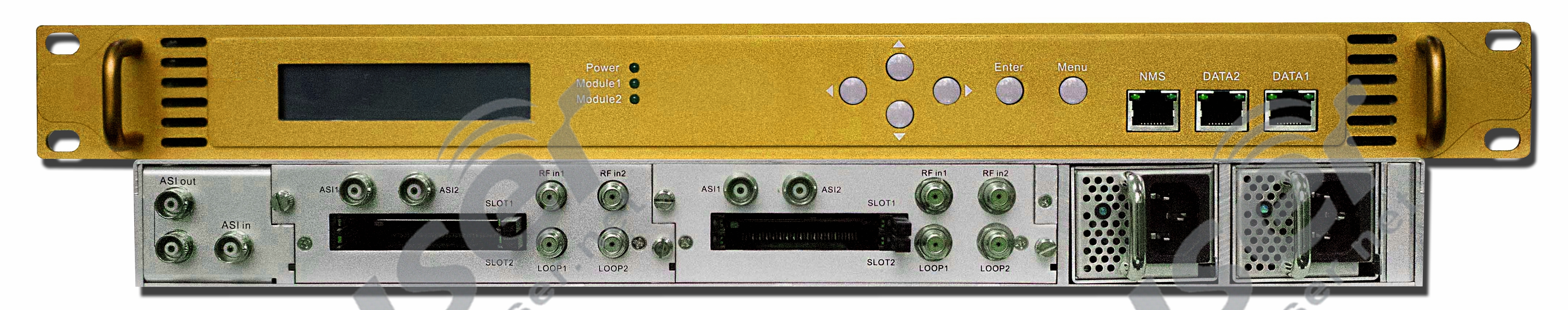
How does Broadcast Satellite Receiver work?
The satellite receiver is used to receive the satellite audio program and input it into the FM broadcast transmitter. And the signal source in the rack room is equivalent to the source of the program broadcasted by the satellite. Satellite TV is a form of the TV program. It can transmit a wireless signal to global TV through the network of communication satellites, radio signals, outdoor FMUSER transmitter antennas, and broadcasting centers. The program source sends the signal to the service provider's Broadcasting Center. The satellite TV receiver is the equipment to receive and decrypt these programs.
There are four common types of satellite receivers
- HD receiver
- General receiver
- Digital receiver with recorder
- Encrypted channel receiver
Tips from Ray - Satellite TV uses a special antenna, usually called a satellite antenna.
Why Broadcast Satellite Receiver is important?
Most of them are used to relay free satellite programs because it is very expensive to rent satellites to transmit their own programs, as FmuserRay researches, the utility model relates to an audio frequency amplifier circuit, a single-phase identification and demodulation circuit, an audio frequency amplifier control circuit, and a multi-phase identification and demodulation circuit. After demodulating the audio modulation signal and management code modulation signal fmuser.-net input by a cable broadcasting signal source fmuser.-net, one channel outputs a management code, one channel outputs a control code through the microprocessor, the other channel outputs an audio signal, and the output control code controls the selection of audio signal. Realize the functional control and management of the receiver, so that cable audio broadcasting can achieve high-quality, multi-channel, multi-functional services.![]()
![]()
Tips from Ray - Satellite audio receiver is specially designed to distribute audio programs through satellite to a radio network, which is the most important part of the radio distribution application
2. Stereo Audio Switcher
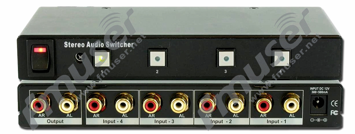
How does Stereo Audio Switcher work?
The audio switcher is used to detect the audio status of each channel circularly. When switching, there is no audio channel to skip automatically fmuser.-net and the switching delay time is optional. Users can set different lengths of switching delay time on the front panel according to their own needs, which provides an effective guarantee for the safe broadcasting of audio. The audio switcher can transmit a multi-channel audio input signal to the output port. In the case of the multi-channel input signal, it can switch any input signal to the output port.![]()
Tips from fmuser-ray - Usually, the audio switcher can complete any switching of 1 ~ 16 input and 1 ~ 16 output. It has an infrared remote control function and RS232 terminal communication control function. It can pre-add the RS485 bus interface, and users can easily complete the signal switching in the demonstration process.![]()
![]()
Why Stereo Audio Switcher is important?
The audio switcher can transmit multiple audio input signals to the output port. In the case of multiple input signals, any input signal can be switched to the output port. These analog and digital audio switchers (some with video) allow you to connect the left and right analog and/or digital audio inputs to one or more outputs. Tips from FM user - When the input is limited, they allow simple switching rather than disconnecting and reconnecting the cable. According to the needs of different industries, the audio switcher not only has an RCA interface supporting an unbalanced audio signal but also has a professional balanced audio XLR interface. www.fmuser.-net The audio switcher is a high-performance intelligent matrix switch equipment specially designed for audio signal display switching fmuser.-net. The stereo audio switcher is widely used in voice engineering, audio-visual teaching, command, and control center, multimedia conference room, and other occasions to complete audio signal switching.![]()
3. Broadcast Audio processor
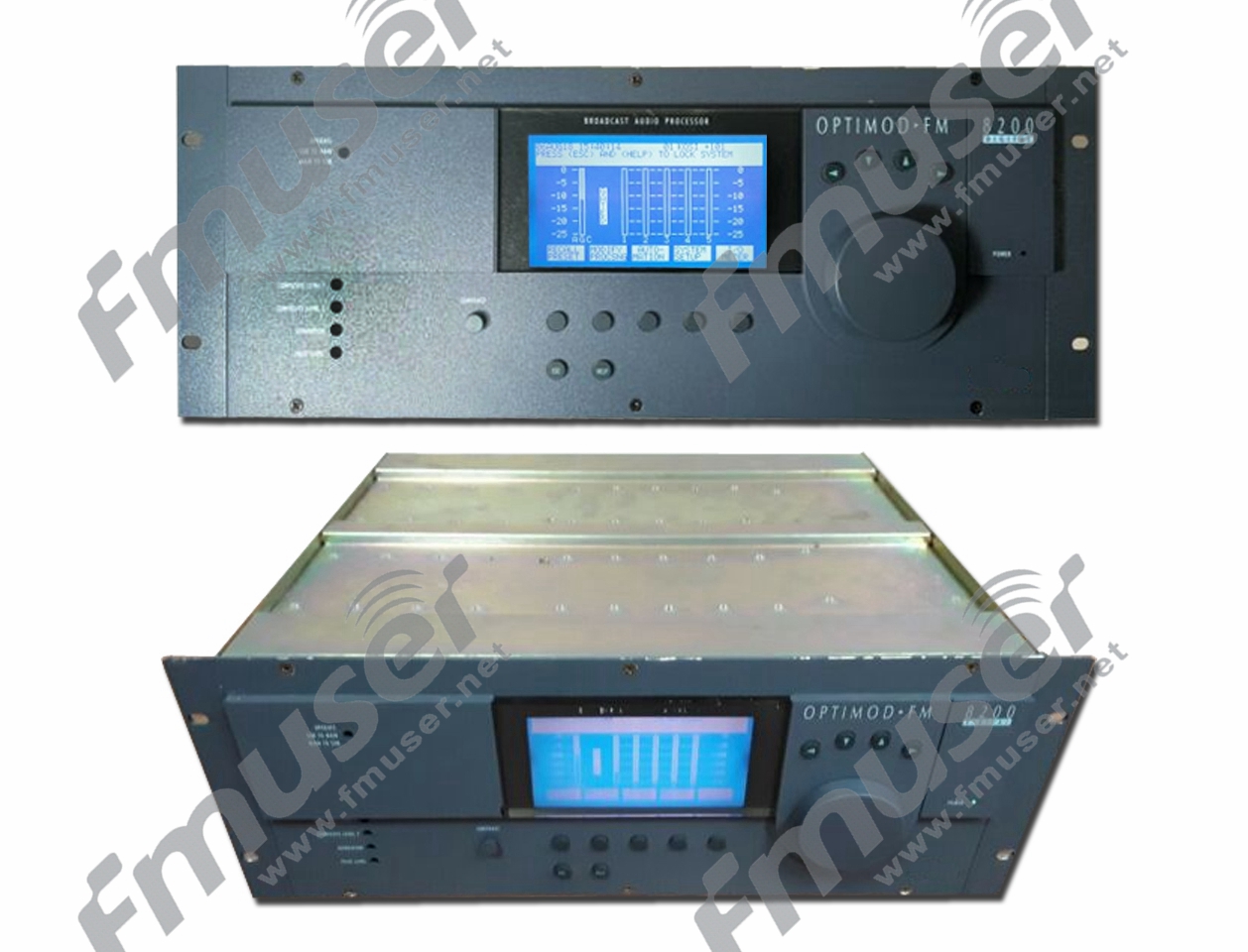
How does Broadcast Audio Processor work?
The audio processor can process the audio signal received from the satellite receiver. Broadcast audio processors contain specialty multi-band compressors/limiters. The Audio Processor will be the last piece of equipment used before the audio signals are transmitted. An audio processor, also known as a digital processor, is a kind of device to achieve a multi-functional audio digital signal processing effect. As FMuserray considers: We often use audio processing devices when using many large electronic devices. www-fmuser-net It can help us control music or score music, make it produce different sound effects in different scenes, increase the shock of music or score music, and at the same time, improve the quality of music Enough to control a lot of audio functions on site. The internal structure of the audio processor is generally composed of input parts and output parts. Its internal functions are more complete, some with drag and drop programming processing modules, which can be built by users freely, fmuser.-net.![]()
In general, the internal architecture of a digital processor is generally composed of an input port and an output part. The functions of the audio processing part are generally as follows: the input part generally includes input gain control (input gain), input equalization (several segments of parameter equalization), input EQ, and so on, Input delay, input polarity, etc, fmuser.-net. The output part generally has several common functions, such as signal input distribution, routing (round), high pass filter (HPF), low pass filter (LPF), equalizer (output EQ), polarity, gain, delay, limiter start level (limit).![]()
Common audio processors can be divided into 4 types:
-
Simple speaker processor
It is used to connect the mixer to the power amplifier instead of analog peripheral equipment for signal processing.
-
The 8-in 8-out multi-functional digital audio processor
It can replace the analog system composed of the small mixer and peripheral equipment in the conference system. It has a network interface and can be connected to the computer through Ethernet for programming and online real-time control.
-
Digital audio processor with network audio transmission function
It is similar to the above two functions, but the audio transmission function of the network is added (CobraNet is generally supported), which can transmit audio data to each other in a LAN.
-
Processing matrix
This kind of processor is an extremely powerful host, which is usually used in large broadcasting systems or conference centers. Large processing matrices are centralized in a computer room, and the processing control of all rooms is completed by the machine in the main computer room. Therefore, fmuser.-net, no matter one or more rooms are used, the processor in the main computer room must be turned on at any time fmuser.-net. This kind of audio network is based on CobraNet or other protocols of Gigabit Ethernet and supports real-time transmission and control.
Why Broadcast Audio Processor is important?
At the simplest level, DSP can be considered as a beautiful and extremely precise tone control. When you combine the processor from fmuser with the measurement function of the real-time analyzer, the tone balance and accuracy of the audio system can be greatly improved by properly trained technicians. Instead of listening to recordings, the voice of humans and musical instruments sound more like performing on the spot. Expert technicians can use stereo equalization to improve the staging and imaging features of your sound system, which can help further improve the authenticity of the listening experience.
FM The audio processing technology is based on the idea that it can realize this benefit while making the audience any illusion of change. Successful audio processing performs the required electrical modifications while presenting a natural and realistic subjective result.
![]()
U For example, the reduction of dynamic range caused by processing makes listening in noisy environments (especially cars) much more difficult. In music with a wide dynamic range, soft music often disappears completely under the effect of background noise. Few listeners listen to music in a completely quiet environment. If you turn the volume up, the larger channels can be uncomfortable later. In cars, the dynamic range cannot exceed 20 dB without causing these problems. The competent audio processing can reduce the dynamic range of the program without adverse side effects.![]()
S In addition, broadcast program materials are usually from a variety of rapidly changing sources, most of which are made without considering other spectrum balances. If the multi-band limit is used correctly, the interference between sources can be automatically consistent. FM-user-Ray knows that just as long films are made to maintain a consistent look, multi-band restrictions and consistency are essential to stations that want to develop unique audio signatures and strong positive personalities. At the end of the day, it all has to do with the experience of the audience.
E In addition, most countries have little tolerance for over modulation, so peak limits must be applied for signals sent to regulated public waves.
R The performance of the processor must be judged based on many different types of program data used in a given format, and finally, the processor must be judged based on its ability to attract and maintain the target audience of a given broadcaster. Long-term listening is irreplaceable, says Ray.![]()
In summary, the benefits of using digital audio processors are:
-
Removing the Equalization in Audio
It can remove the balance added to your music. Automakers have to spend a penny in making cars, Ray says, so they don't use high-quality speakers, they use cheap speakers and add equalizers to make them sound better. This balances "discolors sound" when you add upgraded speakers, which reduces the sound you hear.
-
Summing Your Audio
Many advanced factory audio systems divide music signals into different speaker sizes. Because you want the new speakers to work at the best performance, the processor aggregates the signals into a single full frequency channel. Now, your installer can choose the music frequency that suits them best, says Ray.
-
Enhancing the Listening Experience
Digital latency has been added to your music. Have you ever noticed that your voice seems to have been made from the door closest to you? The processor allows us to delay the sound arrival of each speaker. Now, all of this is reaching your ears at the same time. This will allow your voice to appear in front of you, with stage and image effects comparable to intimate jazz concerts or acoustic performances fmuser.-net.
-
Improving Sound Quality and Output Quality
The carefully crafted equalizer enables us to individually fine-tune each speaker in your new system to maximize its sound quality and output. In summary, we can simply tell you that a carefully designed, carefully built broadcast system and the properly adjusted processor can bring about 100% or higher sound quality improvement.
4. Rack AC Power Conditioner
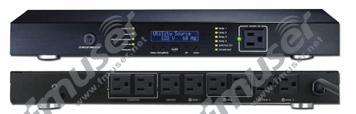
How does Rack AC Power Conditioner work?
The Power conditioner, also known as a line conditioner, can protect equipment from the surge. It is used to protect sensitive loads by eliminating voltage fluctuations such as spikes, transients, and electrical noise. The power conditioner acts as a buffer between the socket and the system to eliminate voltage fluctuations and radio and electromagnetic interference fmuser.-net that may affect the performance of the system, says Ray. A power conditioner is often used in industrial production and laboratory research, and it is also very common in home electronic applications, such as audio equipment.![]() Power conditioners can be electronic or transformer-based, which helps to correct voltage and waveform distortion and eliminate external electrical noise (i.e. frequency and electromagnetic interference) caused by radio and motor equipment. Unlike surge protectors, surge protectors protect devices from voltage spikes, however, surges and spikes still affect some sensitive electronic devices. Radiofrequency interference (RFI), electromagnetic interference (EMI), and voltage fluctuation can also affect the sound and reduce the sound and image quality of equipment. For example, when a musician hears a buzzing sound from his guitar amplifier and his power conditioner can immediately remove it, fmuser.-net it is claimed to be proof of his magical power conditioner. The only problem is that the buzz is usually caused by a ground loop, and the power conditioner has nothing to do with it. A surge protector can effectively prevent the damage of voltage spikes. However, surges and spikes will not only affect some sensitive electronic devices. Radiofrequency interference (RFI), electromagnetic interference (EMI), and voltage fluctuations can also affect sound, entertainment, and office equipment, thereby reducing sound and image quality.
Power conditioners can be electronic or transformer-based, which helps to correct voltage and waveform distortion and eliminate external electrical noise (i.e. frequency and electromagnetic interference) caused by radio and motor equipment. Unlike surge protectors, surge protectors protect devices from voltage spikes, however, surges and spikes still affect some sensitive electronic devices. Radiofrequency interference (RFI), electromagnetic interference (EMI), and voltage fluctuation can also affect the sound and reduce the sound and image quality of equipment. For example, when a musician hears a buzzing sound from his guitar amplifier and his power conditioner can immediately remove it, fmuser.-net it is claimed to be proof of his magical power conditioner. The only problem is that the buzz is usually caused by a ground loop, and the power conditioner has nothing to do with it. A surge protector can effectively prevent the damage of voltage spikes. However, surges and spikes will not only affect some sensitive electronic devices. Radiofrequency interference (RFI), electromagnetic interference (EMI), and voltage fluctuations can also affect sound, entertainment, and office equipment, thereby reducing sound and image quality.![]()
Why Rack AC Power Conditioner is important?
AC power conditioner can protect high-performance audio and video system equipment and has up to 10 or more sockets. AC power conditioner is a typical power conditioner, which can provide a "clean" AC power supply, surge protection, and noise filtering, and avoid equipment damage caused by lightning, surge, and other problems. AC power conditioner is especially suitable for applications where you need to use a noisy power supply, such as home and office applications. Some units have a built-in AVR (audio and video receiver) to compensate for voltage fluctuation. But in fact, UPS (uninterruptible power supply) has its own inverter and battery, which can be used to compensate for low-voltage or high-voltage input power supply, fmuser.-net and provide power filtering and power protection. Its performance is better than that of the AC power conditioner. As Ray says, when power supply filtering is not available, UPS should be the first choice for server and network equipment.![]()
The advantages of power regulation include:
-
Equipment protection
Voltage surge protection through a wire, telephone line, coaxial TV input, and LAN connection can lead to system performance degradation or system failure.
-
Noise elimination
Radio and television stations, mobile devices, electric motors cause noise in the wires - even high current equipment (vacuum, refrigerator) can produce noise.
-
Fluctuation correction of voltage and waveform distortion.
Types and limitations of power conditioners:
-
Passive filter
This is the cheapest type of power conditioner that splits the high-frequency noise component - grounded through a capacitor. These provide very basic noise reduction functions.
-
Balance transformer
This type of power conditioner has a better noise reduction function than the passive inductor-capacitor model (above). It is characterized by an isolation balance transformer, which can balance the AC power supply and produce a more suitable noise reduction effect for audio and video components. Compared with passive filters, they are much more expensive, larger, heavier, and noisy, and their power output is limited due to the damping effect of the balance transformer.
-
AC regeneration
AC regenerative air conditioner will emit a lot of heat when it is running, but the price is higher, but it can better solve the problems related to noise in the audio and video frequency spectrum. Its working principle is similar to that of a generator, which is used to adjust AC voltage, correct waveform symmetry (distortion),
and reduce or eliminate low-order harmonic noise (due to the unbalanced load in AC line) Even or limited noise generated by neighbors to your home), these are the center of known problems. These high-end regulators use automatic voltage stabilizing circuits and microprocessor-controlled variable transformers to provide a completely new AC voltage for your entertainment system without noise-induced fluctuations or surges.
6. Rack Audio Monitor
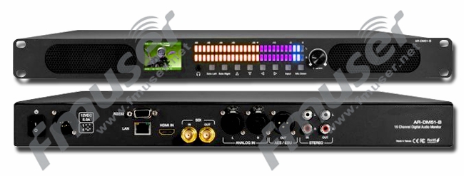
How does Rack Audio Monitor work?
The audio monitor is a kind of active equipment, equipped with speakers, can maximize the output power, front digital panel, can be more easily operated. It is also used to monitor whether the input audio program is correct and to monitor the audio quality before it is finally inputted to the FM broadcast transmitter.
Why Rack Audio Monitor is important?
The audio monitor is often used to monitor the sound from any stereo line-level output, to ensure the control of outdoor background music and strict control of the paging system. General audio monitors in the United States are equipped with DC coupling capacitors at each input to maintain signal integrity without distortion, noise, or ground loops (without a transformer). The rack design enables rack-mounted audio monitors to be installed in very compact applications, which reduces the use of inner spaces.
These units are ideal for use in VTR brackets, mobile production vehicles, teleconference devices, multimedia systems, satellite links, cable TV facilities, and radio stations.
These units are ideal for use in space-critical environments, such as TV facilities, studios, VTR brackets, mobile production vehicles, satellite links, and virtually any rack-mounted environment that requires multi-channel audio monitoring.
7. Rack Digital FM Tuner
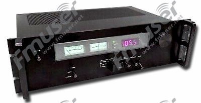
How does Digital FM Tuner work?
The Tuner is used to receive RF signals and convert them to a lower modulated intermediate frequency (IF) or further down-convert to unmodulated baseband.![]() It is a device that receives radio frequency (RF) transmission such as radio broadcast and converts the selected carrier frequency and its associated bandwidth into a fixed frequency suitable for further processing. The transmitting stations and radio receivers receive tiny signals. It is then converted to if through the tuner. It can also be converted by direct synthesis. Then the RF signal is brought to the detector, which acquires the RF signal and brings it to the audio frequency. The audio amplifier then amplifies the signal for playback through headphones or speakers. The tuner selects the resonant frequency by changing the amount of current flowing through it (or something like that). Its job is to separate a sine wave fmuser.-net from thousands of radio signals received by the antenna. In this case, the tuner will be tuned to receive a 680000 Hz signal. The working principle of the tuner is resonance. In other words, Ray says, the tuner resonates and amplifies at a specific frequency, ignoring all other frequencies in the air.
It is a device that receives radio frequency (RF) transmission such as radio broadcast and converts the selected carrier frequency and its associated bandwidth into a fixed frequency suitable for further processing. The transmitting stations and radio receivers receive tiny signals. It is then converted to if through the tuner. It can also be converted by direct synthesis. Then the RF signal is brought to the detector, which acquires the RF signal and brings it to the audio frequency. The audio amplifier then amplifies the signal for playback through headphones or speakers. The tuner selects the resonant frequency by changing the amount of current flowing through it (or something like that). Its job is to separate a sine wave fmuser.-net from thousands of radio signals received by the antenna. In this case, the tuner will be tuned to receive a 680000 Hz signal. The working principle of the tuner is resonance. In other words, Ray says, the tuner resonates and amplifies at a specific frequency, ignoring all other frequencies in the air.![]()
Tuners basically take a reference wave and compare that wave against what the antenna picks up, and there are several kinds of tuners:
- AM
- FM
- Analog TV -NTSC
- Analog TV - PAL
- Digital
Why Digital FM Tuner is important?
The FM tuner can receive FM signals from other stations and input them into the transmitter. It can broadcast programs from other radios. In the early days of broadcasting, the resonance of the antenna and its related inductance and capacitance characteristics were really the items to "dial" the frequency you want to listen to. You don't actually change the length of the antenna, but you can tune the resonance by changing the inductor (coil) or capacitor connected to the antenna. The output signal is an AC voltage, and by rectifying it with a diode (then called a "crystal"), you can extract the signal modulated as a carrier amplitude change. As FMUSER-Ray considers, it's all without any batteries!
FM-But in fact, the antenna in an ordinary modern radio is not a component that "plugs" into the selected broadcast frequency. It's true that the antenna circuit should resonate in the band you're interested in, fmuser.-net but then the broadband signal is mixed with the sinusoidal signal generated internally in the radio in the analog component, which subtracts the frequency and makes the rest possible. Radio operates in a very easy-to-handle frequency band (called if). In the mixer, you can adjust the reception effect in the modern superheterodyne radio receiver. It is much easier to synthesize the precise tuning frequency than to change the resonance of the antenna circuit.
User-The rest is not real physics, but the difference between analog radio and digital radio lies in the circuit. Basically, analog radio extracts modulated signal from intermediate frequency, which is amplified and sent to loudspeaker or radio output. In digital broadcasting, the signal represents the digital version of the audio, just as the wave or MP3 file on the computer is a digital representation, it can be converted back to the analog signal that can be sent to the speaker. The advantage of this is that the bandwidth requirement of digital signals in the air may (potentially) be reduced, fmuser.-net so you can accommodate more signals in the same "airspace", and digital signals are not susceptible to noise. As Ray writes "yes" because unfortunately, many commercial digital radio / TV stations do not, says Ray.
FMUSER. Let me repeat that in "digital" radio, the components that select the receiving frequency are still analog, but the mixed (tuned) frequency is digitally controlled and selected.![]()
Another interesting thing is software-defined radio (SDR), which is the principle of converting if (or in some cases directly antenna frequency) to a digital signal and demodulating it by a full software upgradeable signal processor fmuser.-net. Since it is much easier to program new software than to weld electronic components, this has aroused wide interest among radio enthusiasts.![]()
If you include SDR and apply it without using any intermediate frequency (connecting the antenna directly to the analog-to-digital converter and signal processor), there is a pure software way to adjust the signal source according to your requirements, although it is not the most common way for digital radio to work at present.
8. Audio Fault Alarm
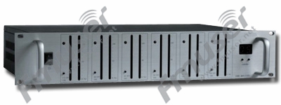
How does Audio Fault Alarm work?
By monitoring the audio input, the audio fault alarm can synchronously monitor multiple audio channels to ensure the quality of the audio input
Why Audio Fault Alarm is important?
In addition to monitoring the audio channel, the most important thing is that the audio fault alarm can detect the audio fault and send the alarm in time.
9. UPS Power Supply
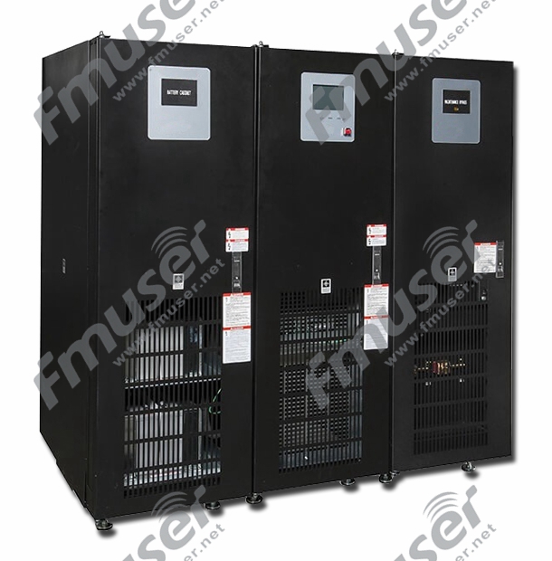
How does UPS Power Supply work?
An uninterruptible power supply (UPS), also known as a standby battery, is very sensitive to the fluctuation of the input power supply which provides backup power when your regular power source fails fmuser.-net or voltage drops to an unacceptable level. It is a kind of standby continuous power supply system that supplies power to the equipment when the main power supply of the equipment is disconnected. UPS consists of a battery, which will "plugin" when the device detects a power failure of the main power supply, providing energy stored in the battery, fmuser.-net, supercapacitor, or flywheel, providing near-instantaneous protection for the interruption of the input power supply so that the power-off device can keep running for at least a short time. UPS equipment also provides anti-surge protection. The size and design of UPS determine how long it will supply power. The small UPS system can provide power for several minutes, which is enough to turn off the computer power orderly, while the large system has enough battery power to last for several hours until it is taken over by the generator.![]()
The common ups are divided into the following three types:
- Standby UPS
- Online UPS
- Online Interactive UPS
Adding an uninterruptible power supply to your radio station is a good way to ensure that the power is interrupted at an important time
- The function of UPS is practical and simple
- Absorb relatively small surge.
- Eliminate noisy power supply.
- Continuous power supply for equipment during line drop.
- The equipment will be shut down automatically in case of power failure for a long time.
- Monitor and record the power status.
- Displays the voltage / current consumption of the device.
- Restart the equipment after a long power failure.
- Displays the voltage on the current power line.
- Provide alerts in some error situations.
- Provide short circuit protection.

Why Uninterruptible Power Supply is important?
An uninterruptible power supply (UPS) is designed to protect critical loads from specific power supply problems, including spikes, power failures, fluctuations, and power outages. UPS is particularly prominent for hardware protection. The UPS power supply in the rack room can stabilize the power supply and supply power to the equipment fmuser-net in a short time to prevent equipment failure or non-operation caused by an unstable grid or to prevent the equipment from stopping working due to power failure or tripping fmuser.-net. In some application scenarios that are vulnerable to the negative impact of power failures, such as telecommunications equipment or computers, sudden power failure will cause machine damage and may cause the loss of some important files, or even casualties. fmuser.-net For a super large professional radio station, UPS is necessary. UPS battery system can protect you and your radio station from damage in case of power failure so that your expensive radio station equipment can automatically fmuser-net run for a period of time without a video monitor until the main power takes over. In hospitals, banks, and other important institutions, these precious minutes may be a matter of life and death. UPS can respond immediately when the main power is cut off, says Ray, and provide powerful power for the system, and then give it to the backup system immediately after it is started and running.![]()
Testing Equipment
RF Dummy Load
During RF system testing, the dummy load, also known as the dummy antenna, serves as a crucial element by simulating the load of the electrical device connected to the radio transmitter's output. It allows for the testing and configuration of the transmitter or receiver without actually radiating radio waves.
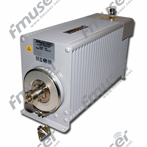
Typically, a dummy load consists of a resistor connected to a radiator that efficiently dissipates power from the transmitter, effectively absorbing the radio frequency (RF) energy and mimicking the impedance characteristics of an antenna. Referred to as RF loads or termination loads, dummy loads provide a controlled and safe means to absorb the RF energy generated by the transmitter when an actual antenna is not connected. This not only prevents unnecessary radiation into the environment but also safeguards the transmitter from potential damage resulting from an unmatched or unconnected transmission line.

In addition to accurately adjusting the transmitter and receiver parameters, the dummy load plays a crucial role in preventing damage caused by misoperation. RF engineers recognize the dummy load as a tool for loading equipment to test amplifiers or RF systems. Using an antenna directly during testing, without any load, not only hampers perfect tuning but also risks damaging the transmitter or receiver due to the heat generated by RF power. By simulating a perfectly tuned antenna connected to the amplifier, the dummy load avoids improper parameter settings or damage to RF equipment. It is strongly recommended to choose a reliable dummy load and use it correctly and promptly during RF equipment testing to minimize unnecessary loss.
Choosing Dummy Loads
Consider the following factors when choosing dummy loads:
- Power Handling Capacity: Determine the power handling capacity of the dummy load. Ensure that it can safely handle the maximum power output of your transmitter without exceeding its limits or causing damage.
- Impedance Matching: Verify that the dummy load matches the impedance of your transmission line, typically 50 ohms. This impedance matching ensures that the transmitter operates properly and minimizes reflections.
- Cooling and Heat Dissipation: Consider the cooling mechanisms and heat dissipation capabilities of the dummy load. Look for designs that efficiently dissipate heat generated by the absorbed RF energy, ensuring that the dummy load remains within safe operating temperatures.
- Connectivity: Verify that the dummy load has the appropriate connectors to match your transmission line. Common connectors include BNC, N-type, or UHF connectors.
- Accuracy: Assess the accuracy of the dummy load's impedance matching to ensure it provides a reliable simulation of an antenna's load. Look for dummy loads that have been tested and verified for their impedance characteristics.
Recommended High Power RF Dummy Loads for You


AM Dummy Loads
AM dummy loads are resistive loads designed to match the impedance of an antenna system in AM broadcasting. They consist of resistive elements enclosed in a heat-dissipating enclosure. Dummy loads are commonly used during equipment testing, transmitter maintenance, or when an actual antenna is not desired or feasible for signal transmission.

How do AM Dummy Loads Work?
AM dummy loads work by providing a resistive load that matches the impedance of the antenna system, typically 50 or 75 ohms. They absorb the RF power from the transmitter, preventing it from being radiated into the air. The resistive elements inside the dummy load convert the RF energy into heat, which is then dissipated using heat sinks or cooling mechanisms.
The absorbed power is dissipated as heat, and the dummy load should be designed to handle the power levels generated by the transmitter without overheating or damage. The heat dissipation capability of the dummy load should be considered to ensure it can handle the power rating of the transmitter being tested.
Choosing AM Dummy Loads
Consider the following factors when choosing AM dummy loads:
- Impedance: Determine the impedance rating required for your application. Choose an AM dummy load that matches the impedance of your antenna system (commonly 50 or 75 ohms) to ensure accurate testing and measurement results.
- Power Handling Capacity: Verify that the dummy load can handle the power rating of your transmitter. Consider the maximum power output of your transmitter and choose a dummy load with a power rating that exceeds your transmitter's maximum power to ensure safe and reliable operation.
- Heat Dissipation: Ensure that the dummy load is designed with adequate heat dissipation mechanisms to handle the power being absorbed. Consider factors such as cooling fins, heat sinks, or fans to dissipate the heat effectively and prevent overheating.
- Build Quality: Choose a well-constructed and reliable dummy load to ensure longevity and accuracy. Look for robust construction, durable materials, and proper connections to ensure a secure and stable connection during testing or transmission.
- Frequency Range: Verify that the dummy load covers the frequency range used in your AM broadcasting system. Ensure that it can handle the specific frequency range of your application without significant impedance variations.
Recommended AM Dummy Loads for You
 |
 |
 |
| 1/3/5 kW | 100kW | 200kW |
RF Power Amplifier Voltage Test Bench
An RF Power Amplifier Voltage Test Bench is a dedicated setup designed specifically for testing and analyzing the performance of RF power amplifiers used in AM transmitters. It allows engineers and technicians to assess the efficiency, linearity, distortion, and other essential parameters of the amplifiers.

* RF Power Amplifier Voltage Test Bench from FMUSER, learn more:
https://www.fmradiobroadcast.com/product/detail/am-transmitter-test-bench.html
How does an RF Power Amplifier Voltage Test Bench Work?
An RF Power Amplifier Voltage Test Bench typically consists of various equipment and components to facilitate accurate testing and measurement of RF power amplifiers. The test bench may include:
- Signal Generator: Provides the input signal to the power amplifier under test. The signal generator generates the modulated or unmodulated RF signal at the desired frequency and power level.
- Power Meter: Measures the output power of the amplifier being tested. It provides accurate power measurement for different frequency bands and helps evaluate the amplifier's performance and linearity.
- Load Termination: A load termination is connected to the output of the power amplifier to provide a matched load and ensure proper testing conditions. It helps dissipate the output power generated by the amplifier without reflecting it back and causing interference or damage.
- Test Signal Monitoring: Equipment such as oscilloscopes or spectrum analyzers may be used to monitor and analyze the output signal quality, distortion, and other characteristics.
The RF Power Amplifier Voltage Test Bench allows engineers to apply controlled input signals, measure the output power, analyze the signal quality, and evaluate the performance of the power amplifiers under various operating conditions.
Choosing an RF Power Amplifier Voltage Test Bench
Consider the following factors when choosing an RF Power Amplifier Voltage Test Bench:
- Compatibility: Ensure that the test bench is compatible with the specific type and frequency range of RF power amplifiers used in your AM transmitters.
- Power Handling Capacity: Verify that the test bench provides the necessary power handling capacity to accommodate the maximum output power of the amplifiers being tested. It should be able to handle the power levels without distortion or damage.
- Measurement Accuracy: Consider the measurement accuracy of the test bench's power meter or other measurement equipment. Accurate measurements are crucial for evaluating and comparing amplifier performance.
- Ease of Use and Control: Look for a test bench that offers user-friendly controls and an intuitive interface for easy operation. Remote control capabilities can also be beneficial to streamline testing and data acquisition.
- Expandability and Flexibility: Consider the ability to expand the test bench's capabilities or adapt it to future requirements. The test bench should allow for future upgrades or modifications to accommodate evolving testing needs.
RF Power Meter
An RF power meter is a measurement instrument used to quantify the power level of RF signals. It is commonly employed in various applications, including radio broadcasting, telecommunications, wireless systems, and RF testing. RF power meters provide accurate power measurements, typically in watts or decibels, enabling users to analyze and optimize the performance of RF systems.

* PM-1A RF power meter from FMUSER, learn more:
https://www.fmradiobroadcast.com/product/detail/pm1a-rf-power-meter.html
How does an RF Power Meter Work?
RF power meters typically employ various techniques to measure the power of RF signals. The specific method used can depend on the frequency range, power level, and accuracy requirements. Here are a few common measurement techniques:
- Thermal Power Sensors: Utilize a thermocouple or thermistor-based sensor to measure the power of the RF signal. The power absorbed by the sensor generates heat, which is converted into an electrical signal proportional to the RF power.
- Diode Power Sensors: Incorporate a diode-based sensor that rectifies the RF signal, converting it into a DC voltage proportional to the RF power level. Diode sensors are often used for a broad range of frequencies and power levels.
- RF Field Strength Measurement: Some power meters operate based on field strength measurement. They use antennas or probes to measure the electric or magnetic field strength of the RF signal. By measuring the field strength, the power can be calculated using specific formulas and assumptions about the antenna's characteristics.
RF power meters may also feature additional capabilities such as frequency measurement, modulation analysis, and data logging to provide more comprehensive analysis of RF signals.
Choosing an RF Power Meter
Consider the following factors when choosing an RF power meter:
- Frequency Range: Ensure that the RF power meter covers the frequency range required for your specific applications. It should be compatible with the frequencies you intend to measure.
- Power Measurement Range: Verify that the power meter offers a suitable power measurement range to accommodate the power levels you expect to encounter. Consider both the maximum and minimum power levels of your RF signals.
- Measurement Accuracy: Evaluate the accuracy and precision of the power meter. Look for specifications such as measurement uncertainty, linearity, and calibration options to ensure accurate measurements in your intended application.
- Measurement Speed: Consider the measurement speed required for your specific tests. Some applications may require fast measurements, while others may not have strict timing constraints.
- Display and User Interface: Assess the display size, clarity, and ease of use of the power meter's user interface. The display should provide clear readings and relevant information, while the controls and menus should be intuitive and straightforward.
- Connectivity and Data Logging: Determine whether the power meter offers connectivity options such as USB, Ethernet, or wireless interfaces for data transfer and control. Data logging capabilities can be beneficial for recording and analyzing power measurements over time.
RF Signal Processing Components
Antenna Power Divider for Multi-layer Antenna
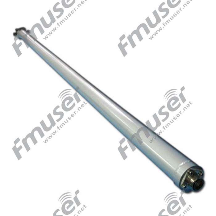
*FMUSER FU-P2 FM Antenna Power Divider - More.
How does Antenna Power Divider work?
An antenna power divider is a device that divides power (equally) between two output ports from one input port or combines two antennas as an array and presents them as a 50-ohm load to a transmitter/receiver combination or transceiver. In the ideal case, a power divider can be considered lossless, but in practice, there is always some fmuser-net power dissipation. The Divider/Combiner can be a quarter-wave section of the transmission line or it can be a can half wavelength section. Theoretically, a power divider and a power combiner can be the exact same component, but in practice, there may be different requirements for combiners and dividers, such as power handling, phase matching, port match, and isolation. Power dividers are often referred to as splitters. While this is technically correct, engineers typically reserve the word “splitter” to mean an inexpensive resistive structure that splits power over a very wide bandwidth but has considerable loss and limited power handling.![]()
Why Antenna Power Divider is important?
When you need to use a multi-layer antenna and your transmitter has only one RF interface, you need to use the antenna power divider. Its function is to divide the single RF interface of the transmitter into "multiple" RF interfaces and connect these interfaces with the multi-layer antenna. At the same time, the power divider will divide the RF power of the transmitter equally into each layer of the antennas, says Ray.![]()
Antenna Tuning Unit
An antenna tuning unit (ATU) is a device used in radio broadcasting systems to optimize the performance of the antenna system. Its primary function is to match the impedance of the antenna to the impedance of the transmission line, ensuring efficient power transfer and minimizing signal reflections. ATUs are especially useful when there are impedance mismatches between the antenna and the transmission line, which can occur due to changes in operating frequency or variations in the antenna's characteristics.

* Antenna Tuning Unit Solution from FMUSER, learn more:
https://www.fmradiobroadcast.com/product/detail/am-antenna-tuning-unit-atu.html
How does an Antenna Tuning Unit Work?
ATUs work by adjusting the electrical properties of the antenna system to achieve a match with the transmission line, typically aiming for a 1:1 impedance ratio. This is achieved through various methods, depending on the design of the ATU. Some ATUs use variable capacitors and inductors to change the electrical length and impedance of the antenna system. By adjusting these components, the ATU can compensate for impedance differences and ensure that the antenna system is properly matched to the transmission line.
The ATU is typically placed between the transmitter and the antenna, and it is often located at the base of the antenna or in close proximity to the transmitter. It can be manually adjusted or automatically controlled, depending on the specific ATU design and capabilities.
Choosing an Antenna Tuning Unit
Consider the following factors when choosing an antenna tuning unit:
- Frequency Range: Determine the frequency range over which the ATU will operate. ATUs are designed for specific frequency ranges, so ensure that the ATU is suitable for the frequency band used by your radio station.
- Power Handling Capacity: Consider the power handling capacity of the ATU. Ensure that it can handle the maximum power output of your transmitter without causing damage or signal degradation.
- Impedance Matching Range: Check the impedance matching range of the ATU. It should be capable of matching the impedance of your antenna system to the transmission line impedance effectively.
- Adjustability: Consider whether you need a manual or automatic ATU. Manual ATUs require manual adjustment, whereas automatic ATUs can adjust the impedance matching automatically based on feedback from sensors or control systems.
- Installation and Compatibility: Ensure that the ATU is compatible with your antenna system and transmission line. Verify the input/output connectors, power requirements, and physical dimensions to ensure proper installation and integration.
RF Cavity Filters
RF cavity filters are specialized filters used in radio frequency (RF) systems to selectively attenuate or pass specific frequency bands. RF cavity filters work based on the principle of resonance within a resonant cavity. They consist of a metallic enclosure with one or more resonant cavities and coupling elements. The resonant cavities are tuned to resonate at specific frequencies, allowing them to attenuate or pass signals within those frequency ranges.

When a signal is applied to an RF cavity filter, the resonant cavities selectively attenuate or pass the frequencies that correspond to their resonant frequencies. The coupling elements control the amount of coupling between the cavities, allowing for precise frequency control and the desired filter characteristics (e.g., bandwidth, insertion loss, selectivity).
Choosing RF Cavity Filters
Consider the following factors when choosing RF cavity filters:
- Frequency Range: Determine the frequency range you need to filter. Choose an RF cavity filter that covers the specific frequency range of your application.
- Filter Characteristics: Different cavity filters have different characteristics such as bandwidth, insertion loss, selectivity, and rejection. Consider the specific requirements of your RF system and choose a filter that meets those requirements.
- Power Handling Capacity: Verify that the RF cavity filter can handle the power levels of your application. Ensure that it can withstand the power without distortion or damage.
- Filter Topology: Consider the filter topology that suits your application. Different cavity filter designs, such as combline filters, interdigital filters, and iris-coupled filters, have different characteristics and performance.
- Environmental Considerations: Assess the environmental conditions the RF cavity filter will be exposed to, such as temperature, humidity, and vibration. Ensure that the chosen filter is suitable for the specific environmental requirements of your application.
- Size and Form Factor: Consider the physical size and form factor of the filter. Ensure that it fits within the available space and can be easily integrated into your RF system.
FM Cavity Filter
An FM cavity filter is specifically designed for filtering FM (Frequency Modulation) signals. It helps attenuate or pass the desired frequency band to ensure proper signal transmission and reception in FM radio systems. FM cavity filters are commonly used in broadcast systems, radio transmitters, and receivers operating in the FM frequency range.
Recommended FM Filters for You
 |
 |
 |
| 500W Bandpass | 1500W Bandpass | 3000W Bandpass |
 |
 |
 |
| 5000W Bandpass |
100kW Bandpass |
200kW Bandpass |
VHF Cavity Filters
VHF (Very High Frequency) cavity filters are designed to filter signals in the VHF frequency band, typically ranging from 30 MHz to 300 MHz. They are commonly used in various applications including television broadcasting, wireless communication systems, and public safety radios operating in the VHF frequency range.
Recommended VHF Filters for You
 |
 |
 |
 |
| 500W Bandpass | 1500W Bandpass | 3000W Bandpass | 5000W Bandpass |
 |
 |
 |
| 10000W Bandpass | 10000W Bandpass | 10000W Bandpass |
UHF Cavity Filters
UHF (Ultra High Frequency) cavity filters are designed for the UHF frequency band, which typically ranges from 300 MHz to 3 GHz. They are widely used in television broadcasting, wireless communication systems, radar systems, and other RF applications operating in the UHF frequency range.
Recommended UHF Filters for You
 |
 |
 |
| 350W DTV Bandpass | 750W DTV Bandpass | 1600W DTV Bandpass |
 |
 |
 |
| 3000W DTV Bandpass |
5500W DTV Bandpass |
20kW Bandpass |
L Band Cavity Filter
An L Band cavity filter is designed to work in the L Band frequency range, typically ranging from 1 GHz to 2 GHz. L Band is commonly used in satellite communication, aeronautical applications, and wireless systems requiring long-range communication.
Recommended FM Transmitters for You
 |
| 3kW Bandpass |
RF Hybrid Couplers
RF hybrid couplers are passive devices used in RF systems to combine or split signals while maintaining isolation between the input and output ports.

How RF Hybrid Couplers Work
RF hybrid couplers work based on the principle of power division and combining within a four-port network. They consist of two input ports (often referred to as the main and coupled ports) and two output ports. The main port is connected to the main signal source, while the coupled port connects to the coupled signal. The remaining two ports are the output ports.
The RF hybrid coupler operates by splitting the power from the main port into two paths: one that goes directly to one output port and another that is coupled to the other output port. This allows for power division and signal coupling while maintaining high isolation between the input and output ports.
The amount of power split and coupling is determined by the design and specifications of the hybrid coupler, such as the coupling ratio and isolation. The coupling ratio determines the distribution of power between the output ports, while isolation ensures minimal signal leakage between the input and output ports.
Choosing RF Hybrid Couplers
Consider the following factors when choosing RF hybrid couplers:
- Frequency Range: Determine the frequency range you need to work with. Choose an RF hybrid coupler that covers the specific frequency range of your application.
- Coupling Ratio: Evaluate the coupling ratio required for your system. The coupling ratio determines the distribution of power between the output ports. Choose a hybrid coupler with the appropriate coupling ratio based on your system's needs.
- Isolation: Consider the required level of isolation between ports. Higher isolation ensures minimal signal leakage between the input and output ports. Choose a hybrid coupler with sufficient isolation for your application.
- Power Handling Capacity: Verify that the RF hybrid coupler can handle the power levels of your application. Ensure that it can withstand the power without distortion or damage.
- Environmental Considerations: Assess the environmental conditions the hybrid coupler will be exposed to, such as temperature, humidity, and vibration. Ensure that the chosen coupler is suitable for the specific environmental requirements of your application.
- Size and Form Factor: Consider the physical size and form factor of the hybrid coupler. Ensure that it fits within the available space and can be easily integrated into your RF system.
VHF Couplers
VHF (Very High Frequency) couplers are designed to operate in the VHF frequency range, typically from 30 MHz to 300 MHz. They are used to combine or split VHF signals while maintaining high isolation between ports. VHF couplers are commonly used in applications such as television broadcasting, wireless communication systems, and RF amplifiers operating in the VHF frequency range.
Recommended VHF Couplers for You


UHF Couplers
UHF (Ultra High Frequency) couplers are designed for the UHF frequency band, which generally spans from 300 MHz to 3 GHz. UHF couplers enable the combining or splitting of UHF signals while maintaining isolation between ports. They find applications in television broadcasting, wireless communication systems, radar systems, and other RF systems operating in the UHF frequency range.
Recommended UHF Couplers for You
 |
 |
 |
| 1-5/8” 5kW 3dB Hybrid UHF | 1-5/8" 8kW 3dB 4 Ports Hybrid FM | 1-5/8" 15kW 3dB Hybrid UHF |
 |
 |
 |
| 1-5/8" 20kW 3dB Hybrid UHF |
3-1/8" 25kW 3dB Hybrid UHF |
4-1/2" 40kW 3dB Hybrid UHF |
L Band Coupler
L Band couplers are specifically designed for the L Band frequency range, typically ranging from 1 GHz to 2 GHz. They are used to combine or split L Band signals while maintaining isolation between ports. L Band couplers are commonly used in satellite communication systems, aeronautical applications, and wireless systems requiring long-range communication.
Recommended L-band Couplers for You
 |
 |
| 1-5/8" 4kW 3dB Hybrid L-band | 1-5/8", 7/16 Din, 3 Ports 4kW 3dB Hybrid L-band |
Transmitter Combiners
Transmitter combiners are devices used in RF systems to combine the output signals of multiple transmitters into a single transmission line.

How Transmitter Combiners Work
Transmitter combiners work by combining the output signals of multiple transmitters into a common transmission line while maintaining proper impedance matching and isolation. They typically consist of filters, dividers, and combiner networks.
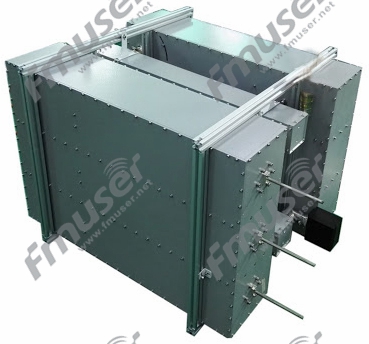
The filters in a transmitter combiner are used to isolate the individual transmitter outputs and prevent unwanted intermodulation or interferences. The dividers split the power from each transmitter and direct it to the combiner network. The combiner network merges the signals into a single transmission line, ensuring proper impedance matching and minimizing signal loss.
Transmitter combiners are designed to provide high isolation between the transmitter outputs, preventing cross-talk or interference between them. They also maintain impedance matching to ensure efficient signal transmission and reduce reflections.
Choosing Transmitter Combiners
Consider the following factors when choosing transmitter combiners:
- Frequency Range: Determine the frequency range of your transmitters. Choose a transmitter combiner that covers the specific frequency range of your transmitters.
- Number of Transmitters: Determine the number of transmitters you need to combine. Choose a transmitter combiner with sufficient input ports to accommodate all your transmitters.
- Power Handling Capacity: Verify that the transmitter combiner can handle the power levels of your transmitters. Ensure that it can withstand the combined power without distortion or damage.
- Isolation and Insertion Loss: Evaluate the isolation and insertion loss characteristics of the transmitter combiner. Higher isolation ensures minimal interference between transmitter outputs, while lower insertion loss ensures efficient signal transmission.
- Environmental Considerations: Assess the environmental conditions the transmitter combiner will be exposed to, such as temperature, humidity, and vibration. Ensure that the chosen combiner is suitable for the specific environmental requirements of your application.
- Size and Form Factor: Consider the physical size and form factor of the transmitter combiner. Ensure that it fits within the available space and can be easily integrated into your RF system.
FM Combiners
FM combiners are specifically designed for FM (Frequency Modulation) transmitters. They allow for the combination of multiple FM transmitter outputs into a common transmission line. FM combiners are commonly used in broadcast systems, FM radio stations, and other applications that require the simultaneous operation of multiple FM transmitters. >>Learn More
Recommended FM Transmitter Combiners for You
Balanced type:
 |
 |
 |
 |
| 7/16 Din, 4kW, Model A | 7/16 Din, 4kW, Model B |
 |
 |
 |
| 40kW 3-1/8" | 3 or 4-Cav, 3-1/8", 50kW |
Start type:
 |
 |
 |
| 7/16 Din, 1kW | 7/16 Din, 3kW | 7/16 Din, 6kW |
 |
 |
| 1-5/8", 10kW | 3-1/8", 20kW |
VHF Combiners
VHF (Very High Frequency) combiners are designed to combine the outputs of multiple VHF transmitters. They enable the efficient combination of VHF signals into a single transmission line, minimizing signal loss and interference. VHF combiners are commonly used in television broadcasting, wireless communication systems, and public safety radio networks operating in the VHF frequency range. >>Learn More
Recommended VHF Transmitter Combiners for You
Balanced type:
 |
 |
 |
 |
| 3-1/8", 6-Cav, 24kW | 3 or 4-Cav., 3-1/8", 40kW |
Star type:
 |
 |
 |
 |
| 4 or 6-Cav, 7/16 Din, 1kW | 4 or 6-Cav, 1-5/8", 3kW | 4 or 6-Cav, 1-5/8", 6kW | 3 or 4-Cav., 1-5/8", 10kW |
UHF Combiners
UHF (Ultra High Frequency) combiners are designed for the combination of UHF transmitter outputs. They allow for the efficient merging of UHF signals into a common transmission line, ensuring proper signal transmission and minimizing interference. UHF combiners find applications in television broadcasting, wireless communication systems, radar systems, and other RF systems operating in the UHF frequency range. >>Learn More
Recommended UHF Transmitter Combiners for You
Balanced type:


Others:
 |
 |
 |
 |
| 7-16 Din 6-Cav Cabinet 1kW | 1-5/8" or 3-1/8", 8/20 kW Stretchline | 3-1/8", 4-Cav, 15/20 kW Star-type |
L Band Combiners
L Band combiners are specifically designed for the combination of L Band transmitter outputs. They enable the simultaneous operation of multiple L Band transmitters by merging their signals into a single transmission line. L Band combiners are commonly used in satellite communication systems, aeronautical applications, and wireless systems requiring long-range communication in the L Band frequency range. >>Learn More
Recommended UHF Transmitter Combiners for You
 |
| 1-5/8" 6-Cav 3-Chan 3kW |
Waveguide Components
Antenna Waveguide Dehydrator
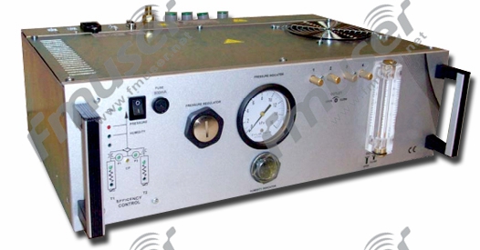
*Antenna waveguide dehydrator
How does Waveguide Dehydrator work?
Waveguide dehydrator is used to provide dry compressed air for itself and signal transmission towers (such as microwave, radar, antenna system, TV satellite ground) and related components in various fields. It is worth noting that in order to ensure the quality of signal transmission, the compressed air pressure provided by the general waveguide dehydrator fmuser.-net will be higher than the atmospheric pressure. On the one hand, it prevents the water from entering, avoids the condensation of the air, and achieves the driest effect;![]() on the other hand, it avoids the influence caused by the weather. A small pressure vessel is installed in the waveguide dehydrator to ensure the stop-start cycle rather than the continuous operation of the integral compressor.
on the other hand, it avoids the influence caused by the weather. A small pressure vessel is installed in the waveguide dehydrator to ensure the stop-start cycle rather than the continuous operation of the integral compressor.![]()
The differential pressure switch controls the operation of the compressor. The container stores dry air at elevated pressure and are pumped into the waveguide at a lower pressure set by the regulator. At present, many waveguide dehydrators on the market have built-in electronic timing and humidity monitoring systems, which can detect some unexpected problems of waveguide dehydrators at the fastest speed, that is, the problem caused by insufficient storage of dry air. Based on Ray's research, the operator can deliberately introduce a small amount of air to ensure that the air in the waveguide system is replaced regularly as needed to maximize the benefits of the waveguide dehydrator.![]()
Why Waveguide Dehydrator is important?
Because the particles in the waveguide will cause reflection and signal loss or attenuation, the dehydrator can keep a clean, dry, and particle-free environment in the waveguide, and let the airflow in the feed pipe, so as to prevent the antenna SWR from being too high or wire short-circuited caused by humidity. Therefore, the waveguide dehydrator plays an important role in most communication applications.![]()
Electrical Control Panel Part
In the electrical control panels part, 6 primary equipment is included, and they are (click to visit):
- Knife Switch
- Electricity Meter
- Power and Energy Monitoring Meter
- Surge Protection Device
- Circuit Breaker
- Programmable Logic Controller
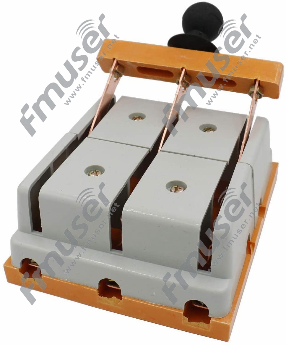
*A Two-pole Knife Switch
How does Knife Switch work?
A knife switch (also known as knife switch or disconnector) is a kind of switch with moving contact -- knife switch, which is wedged (or separated) with the fixed contact -- knife holder on the base to connect (or disconnect) the circuit. A knife switch is one of the most simple and widely used low-voltage electrical appliances in manual control apparatus. It is generally used in AC and DC low-voltage (no more than 500V) circuits that do not need to be fmuser.-net cut off and closed frequently. Under the rated voltage, its working current cannot exceed the rated value fmuser.-net. In the machine tool, the knife switch is mainly used as a power switch, it is generally not used to turn on or cut off the working current of the motor. The commonly used knife switches are HD type single throw knife switch, HS type double throw knife switch (knife switch), HR type fuse knife switch, HZ type combination switch, HK type knife switch, HY type reverse switch, and HH type iron case switch, etc, says Ray-fmuser.![]()
Why Knife Switch is important?
- The knife switch isolates the power supply to ensure the safety of circuit and equipment maintenance or as infrequently connecting and breaking the load below the rated current.
- The knife switch breaks the load, such as infrequently connecting and breaking the low-voltage circuit with small capacity or directly starting the small capacity motor.

- When the knife switch is in the off position, it can be obviously observed, which can ensure the safety of the circuit maintenance personnel.
The knife switch isolating the power supply is also called the disconnecting switch. Knife switch for isolation is generally a no-load on-off device, which can only make or break "negligible current" (refers to the capacitive current of the bus with voltage, short cable, or voltage transformer). Some knife switches have certain on-off capabilities. When their on-off capability is suitable for the required on-off current, they can turn on or off part of electrical equipment fmuser-net or complete equipment under non-fault conditions. The knife switch used as the disconnector must meet the isolation function, that is, the switch fracture is obvious, and the fracture distance is qualified. During the maintenance of electrical equipment, it is necessary to cut off the power supply to make it separate from the live part, and maintain an effective isolation distance. What Ray found: It is required that the withstand voltage level of overvoltage can be withstood between the split sections. As Ray says. the knife switch is used as a switching device to isolate the power supply.
Knife switch and fuse are connected in series to form a unit, which is called knife switch fuse group or disconnecting switch fuse group; when the movable part (moving contact) of knife switch is composed of fuse carrying parts with fuse link, it is called fuse knife switch or fuse disconnecting switch fmuser. net. The switch fuse is combined with auxiliary components, such as operating lever, spring, arc knife, etc. The load switch has the ability to turn on or off the load current under non-fault conditions and has a certain short-circuit protection function.![]()
2. Electricity Meter
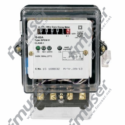
*A Traditional Electricity Meter
How does Electricity Meter work?
An electricity meter (also known as an electricity meter, electric meter, electrical meter, or energy meter) is a device to measure the electrical energy consumed by residential, business, or electric equipment fmuser-net. Electricity meters are divided into digital meters and analog meters. The installation and final billing of electricity meters are usually for power companies. The staff of power companies will install electricity meters where they need to use electricity meters, and periodically monitor and charge the users through the parameters on the meters. When your home gets electricity from a wire, a set of pinions in the meter moves. The revolution is recorded by the dial you see when you look at the meter fmuser.-net. The rotational speed is determined by the consumed power. The working principle of some other energy measuring devices, says Ray, are similar to electric meters, such as gas meters, is to measure the force of moving gas in the pipeline. With the increase of gas flow, the dial rotates faster, which means more gas is used. It is worth noting that electricity reading is often in kWh and whether it is a digital meter or an analog meter, the kWh of electricity consumed displayed on the display will not be reset. When the staff of the power company read the electricity consumed in the current month (week) displayed on the meter, they only need to subtract the number from the end of the month to calculate the bill amount of each household and charge.
Why Electricity Meter is important?
You may not pay special attention to the changes of parameters on the meter, but you should know how to observe the numbers displayed on the meter panel, so that you can monitor how much energy you use in each month or week compared with the previous month or week, and check the bill amount you are required to pay by the power company and calculate by yourself through some simple calculations The difference between the actual amount of the bill, to ensure that do not spend unnecessary money.
Although the types of electricity meters on the market are not uniform at present, there are many advantages of using digital electricity meters for both power consumers and power energy suppliers. For consumers, the electricity price in the period of strong demand (6:00 p.m - 11:00 p.m) is often lower than that in the period of low demand (0:00 a.m - 7:00 p.m) a. If you use the traditional automatic meter reading (AMR), you will spend more on the electricity bill, because AMR will track your electricity consumption and the power company will charge you electricity based on the average price of the previous cycle fmuser.-net. The use of digital meters can accurately monitor the power consumption so that your power energy supplier can determine the specific number of electricity you use, and also determine when you use the electricity, so as to avoid unnecessary electricity bill expenses. For power energy suppliers, the use of smart meters is convenient for their staff. Instead of counting the electric power consumed by each household, they can directly read the parameters on the meter panel through remote communication, which greatly reduces the operation cost and labor cost of power companies.![]()
3. Power Monitoring and Control Equipment
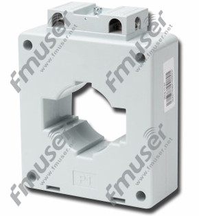
*Window Type Current Transformer
How does the Current Transformer work?
Current transformer (CT) is a kind of instrument transformer, which can convert high voltage current to low voltage current, that is, convert current from higher value to proportional current and then to lower value. According to its functional architecture, current transformers can be divided into a bar type, wound type, and window type. According to its nature, CT can be divided into two types: protective current transformers and measuring current transformers fmuser- net. Among them, protective current transformers are responsible for measuring current, energy, and power (used together with other measuring equipment), while measuring current transformers are used together with a trip coil, relay, and other protective equipment.![]()
Why the Current Transformer is important?
The current transformer is one of the important elements of the power system, which is widely used in the measurement and monitoring of high current and high voltage. By using a standard ammeter, the current flowing in the AC transmission line can be safely monitored. For example, the current transformer can be used as the core driver of many large commercial and industrial power meters. As Ray says, current transformers are also used to provide current proportional to power to these devices and to isolate the measuring instruments from high voltage circuits.![]()
4. Surge Protection Device
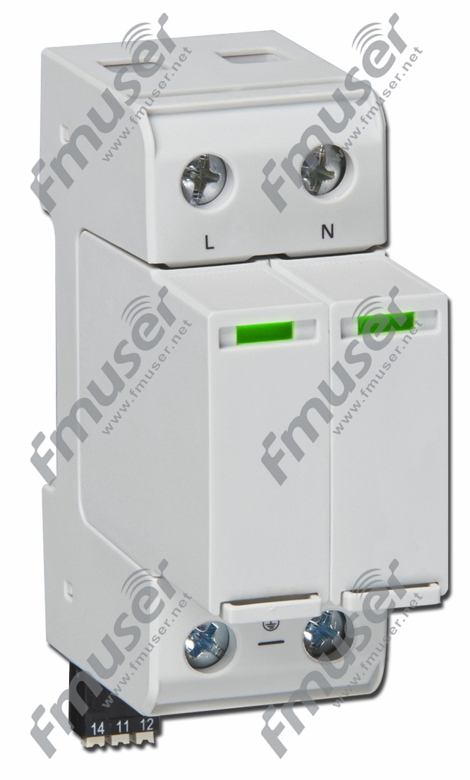
*Surge Protection Device
How does Surge Protection Device work?
Surge protection equipment (SPD), formerly known as transient voltage surge suppressor (TVSS) or secondary surge suppressor (SSA), is the most commonly used and effective type of overvoltage protection, which is designed to prevent voltage spikes fmuser .net or "transients" from damaging electronic equipment, which is usually connected in parallel on the power supply circuit of load. As an important part of the electrical installation protection system, when transient voltage (such as a lightning strike or power line damage) appears suddenly on the protection circuit, SPD limits the transient voltage and transfers the current back to its source or ground. When the voltage reaches a certain point, the surge protector can simply redistribute additional energy by virtue of the function of a pressure-sensitive valve in essence. With the correct voltage, the current will flow normally. Surge protection equipment fmuser -net can also be used at all levels of the power network, SPD is in a high impedance state under normal operating voltage and does not affect the system. When transient voltage occurs on the circuit, SPD enters the on the state (or low impedance) and transfers the surge current back to its source or ground. This will limit the voltage or clamp to a safer level. After transient transfer, SPD will reset to its high impedance state automatically.![]()
One should compare different available devices once identifying the power distribution system to which the SPD is to be connected, 5 things need to be taken into consideration:
- Maximum Continuous Operating Voltage (MCOV).
- Voltage Protection Rating (VPR) or Voltage Protection Level (Up).
- Nominal Discharge Current (In) Rating.
- Indication Status.
- Surge Current Capacity or Maximum Surge Rating.
Why Surge Protection Device is important?
Surge protection device (SPD) can prevent machine shutdown, improve the system and data reliability and eliminate equipment damage caused by transient and surge of power and signal lines. The surge may be generated from outside, such as the generation of lightning or the internal generation of electrical load conversion. The sources of these internal surges (65 percent of all transients) can include open and closed loads, operation of relays or circuit breakers, heating systems, motors, and office equipment, as Ray considers.
Surge protection device (SPD) is applicable to almost any facility in the industry, commerce, and residence, and the following are some typical surge protection equipment applications:
Communication circuit, alarm signal circuit, home appliances, PLC distribution, standby power supply, UPS, equipment monitoring, critical load (under 1000 Volts), medical equipment and HVAC equipment, etc
According to national electrical regulations (NEC) and ANSI / UL 1449, SPD is specified as follows:![]()
-
Type 1: Permanent Connection
It is designed to be installed between the secondary of the service transformer and the line side of the service disconnect overcurrent equipment (service equipment). Their main purpose is to protect the insulation level of the electrical system to prevent external surges caused by lightning or switching of the common capacitor banks.
-
Type 2: Permanent Connection
It is designed to be installed on the load side of the service disconnected over current equipment (service equipment), including the location of the brand panel. Their main purpose is to protect sensitive electronic equipment and microprocessor-based loads from the impact of residual lightning energy, motor-generated surge, and other internal surge events.
-
Type 3: SPD Connection
Using point SPD installed at a minimum conductor length of 10 m (30 feet) from the electrical service panel to the point of use. Examples include cable connections, direct plug-in, and socket type surge protection devices
5. Circuit Breaker
*Electric Mini Circuit Breaker
How does Circuit Breaker work?
The circuit breaker is essentially a reset fuse. Inside each circuit breaker is a spring hooked on a small piece of solder (a fusible alloy). Each circuit breaker is connected to a wire running through the house. The current flows through the house through the solder. The circuit breaker will not trip and the solder will melt when the connected wiring is in danger of overheating. As long as the current jumps above the safe level, fmuser-net the circuit can be cut off to avoid overheating, melting, and potential fire. Different from the fuse that can only be operated once and must be replaced, the circuit breaker can be reset automatically fmuser.-net or manually after the alloy is cooled to resume normal operation. The manufacturing process of circuit breakers makes them well used in circuit devices of various sizes, such as single household appliances or urban high-voltage power supply circuits. Circuit breakers may be more effective than safety switches, but they are not switches. As Ray says, the circuit breaker and safety switches are not interchangeable. Therefore, it is not recommended to use circuit breakers as switches.![]()
Why Circuit Breaker is important?
A circuit breaker is a safety device that prevents damage to the motor and wires when the current flowing through the circuit exceeds its design limit. This is achieved by removing current from the circuit in the event of an unsafe condition. Unlike the switch, the circuit breaker automatically performs this operation and turns off the power immediately, or turns off the power immediately. In this way, it can be used as an automatic service protection device against fire and electric shock.
6. Programmable Logic Controller
*Programmable Logic Controller Device
How does the Programmable Logic Controller work?
Programmable logic controller (PLC) is a kind of industrial automation solid-state general control electronic equipment, and it is a flexible and powerful control solution, which is suitable for almost all applications. Common PLC includes CPU, analog input, analog output, and DC output fmuser.-net. In practical application, PLC can be understood as a kind of digital computer. Its function is to make decisions based on logic fmuser.-net for the whole automatic production process, control industrial machines, monitor the inputs from pressure sensors, temperature sensors, limit switches, auxiliary contacts, and pilot devices, and then connect them from the connected sensors or input devices Receive the signal, process the data, and trigger the output according to the pre-programmed parameters.![]()
The general components of PLC include:
- HMI – in order to interact with PLC in real-time, users need HMI or a human-machine interface. These operator interfaces can be simple displays with text readers and keyboards, or large touch-screen panels more similar to consumer electronics, but either way, as Ray says, they allow users to view the information in real-time and input it into the PLC.
- Communication – in addition to the input and output devices, the PLC may need to be connected to other types of systems. For example, a user may want to export application data recorded by a PLC to a monitoring and data acquisition (SCADA) system that monitors multiple connected devices fmuser-.net. PLC provides a series of ports and communication protocols to ensure that PLC can communicate with these other systems.
- Programming Device – used to input programs into the memory of the processor.
- Power Supply – Although most PLCs operate at 24 VDC or 220 VAC, some have isolated power supply.
- CPU – check the PLC regularly to prevent errors and perform functions such as arithmetic and logic operations.
- Memory – system ROM permanently stores fixed data used by CPU, while RAM stores input and output device information, timer value, counter, and other internal devices.
- I / O Section – an input section that tracks field devices such as switches and sensors.
- O / P Part – this part provides output control for pumps, solenoids, lamps, and motors.

Why the Programmable Logic Controller is important?
Five things to understand when programming PLC:
- Understand how programs and I / O scans work
- Learn how to handle I / O
- Understanding internal memory addressing
- Familiar with instruction set (ladder diagram)
- Familiar with programming software (create a project, add logic, download to the controller, monitor online and edit online)
According to the input and output, PLC can monitor and record the running data, such as the productivity or working temperature of the machine, automatically start and stop the process, and generate alarms when the machine fails.![]()
In short, PLC is the modular "brain" of the automation process, which you can plug into various settings. They are robust and can withstand harsh conditions such as high temperature, cold, dust, and extreme humidity .fmuser.-net, but also their programming language is easy to understand, so they can be programmed easily. In the case of switching under load, fmuser.-net the relay will cause a high-temperature arc between the contacts, which will make the contacts in the relay degenerate due to closing, and eventually lead to equipment failure. Replacing the relay with a PLC helps to prevent overheating of the contacts.
The programmable controller has become the main automation method in many industries and applications, which can provide accurate, reliable, and easy to modify control. In addition to discrete and procedural functions, Ray also finds that the controller can perform complex tasks such as motion, data logging, web server access, and e-mail.![]()
Peripheral Supporting Part
In the peripheral part, 9 equipment is included, and they are (click to visit):
- Air Conditioner
- Electrical Junction Box
- Emergency Light
- Clock
- Surveillance Camera
- Indoor Thermometer
- Digital Humidity Meter
- Fire Extinguisher
- Exhaust Fan
The equipment in the peripheral supporting part is used to display the condition of the rack room and optimize the better working environment for the broadcast equipment in a radio rack room fmuser.-net, including providing cool and dry air, fire extinguishing, etc.
1. Air Conditioner
How does Air Conditioner work?
For the radio room, air conditioning is an essential cooling tool. Some radio equipment, such as high-power FM radio transmitter, will inevitably heat up when it runs for a long time. The cold air from the air conditioning can well control the whole temperature of the room, cool down the radio equipment, and avoid unnecessary machine failure caused by too high temperature, says Ray.![]()
2. Electrical Junction Box
How does Electrical Junction Box work?
The junction box is a device that uses a metal or plastic shell as the common junction point of the branch circuit, which can accommodate and safely protect the electrical connection of the structure from the damage caused by some natural affections such as corrosive elements or environment, as well as humanistic malicious or unintentional tampering fmuser.-net. The junction box is also an important part of the transmission system in the transmitter room of the radio station, and these electrical shells are usually used to protect the electrical connection of the structure. According to FMUSERRay's searches, there are two sizes: a three-wire box with a size of 2 inches by 3 inches and a depth of 2.5 inches, and a box with five or more wires with a size of 2 inches by 3 inches and a depth of 3.5 inches.![]()
3. Emergency Light
How does Emergency Light work?
Emergency lighting refers to the light source device with an independent battery power supply which is started in case of loss of external power (such as power failure, fire, etc.). In non-emergency situations, emergency lighting will automatically charge. Though the brightness of the emergency lighting light source is only 19% to 21% of the typical light source brightness fmuser.-net, it extends the Sustainable Lighting duration of emergency lighting. Emergency lighting can help the maintenance personnel evacuate safely from the emergency as fast as possible.![]()
4. Clock

How does a Clock work?
The Clock generally refers to any periodic system used to measure, verify, hold, and indicate the time of the equipment. Generally, the clock has a minute and a second. The clock takes minutes as the smallest scale unit and takes every 12 hours as a cycle fmuser.-net. The clock is also one of the indispensable pieces of equipment in the equipment list of the radio room, which can help the equipment maintenance personnel set the equipment according to the specific time.
5. Surveillance Camera
How does Surveillance Camera work?
The monitoring camera is actually a part of closed-circuit monitoring. For the radio station, the operation status of the equipment in the rack room needs a clear and real-time system for remote monitoring. In this way, we can not only understand the real-time operation status of the broadcasting equipment, but also facilitate data observation and information collection fmuser.-net, but also make a timely response when the equipment in the rack room breaks into unexpected conditions. The maintenance personnel in the computer room no longer need to run back and forth when the equipment in the rack room goes wrong, which saves the labor cost and improves the work efficiency of the equipment, says Ray.![]()
A general closed-circuit monitoring system consists of the following elements
- monitor
- Digital Video Recorder
- movie camera
- Cable
6. Indoor-Outdoor Thermometer
How does Indoor-Outdoor Thermometer work?
An indoor and outdoor thermometer is a kind of thermometer that can provide real-time indoor and outdoor temperature. It allows you to measure the external temperature without going out of a confined space. Of course, it needs a remote sensing device to measure it. In addition to measuring the outdoor temperature, it can also measure the internal temperature, humidity, or air pressure of the confined space. The indoor and outdoor thermometer is especially suitable for use in extreme weather conditions fmuser.-net. For radio stations, the purchase of an indoor and outdoor thermometer can help the maintenance personnel of the computer room to determine whether the internal conditions of the computer room are suitable for the operation of the equipment and make timely adjustments because some invisible atmospheric parameters (such as air humidity and temperature) are too high or too low, which will directly affect the operation of those broadcasting equipment bought at a high price or even guide the operation of the equipment damage to core components, says Ray.![]()
7. Fire Extinguisher
How does Fire Extinguisher work?
The fire extinguisher is a kind of portable equipment that can extinguish the flame caused by the combustion of various combustible materials by discharging non-combustible materials (such as water, carbon dioxide, etc.) A common fire extinguisher is a hand-held cylindrical pressure vessel. You just need to pull out the pull ring, hold the nozzle fmuser-.net, and aim at the combustibles to put out the fire. For the room of the radio station, a fire extinguisher is necessary. Timely fire fighting can minimize the loss. After all, no one wants to burn down the millions of broadcasting equipment in one fire.![]()
- Foam Fire Extinguisher
- Dry Powder Fire Extinguisher
- Cleaner Fire Extinguisher
- Carbon Dioxide Fire Extinguisher
- Water Mist Fire Extinguisher
- Wet Chemical Fire Extinguisher
8. Exhaust Fan
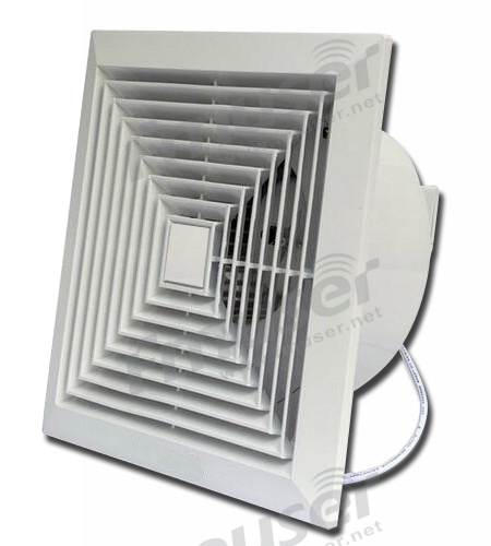
How does Exhaust Fan work?
An exhaust fan refers to a kind of equipment used to exhaust harmful substances (such as excess water, pungent smell, toxic smoke, etc.) in the indoor air to the outdoor by extraction. In the machine room of the radio station, some equipment will inevitably run abnormally due to too many impurities in the air, especially moisture fmuser.-net. A professional radio room should have a very dry, ventilated, cool environment for the broadcast equipment, and the exhaust fan plays such a role to provide the equipment a dry, ventilated and clean environment.
Cable Connection Part
In the peripheral part, 6 equipment is included, and they are:
- Audio Cable
- USB Cable
- RS-232/486 Control Line
- Power Plug-in
- Network CableEquipment Label
Different broadcast equipment shares different interfaces, so different connecting wires are needed, fmuser.-net, for example, a USB cable needs to connect with a USB interface, and a radio transmitter needs to use an RS232/486 control line to connect with the power supply fmuser.-net. The connecting wire is one of the most inconspicuous peripheral auxiliary devices. But, without these connecting wires, those expensive broadcast devices can not start and operate normally, says Ray.![]()
1. Audio Cable
The audio cable is used to ensure the input and output of the audio signal
2. USB Cable
The USB cable is used to connect the device that needs to be connected to the computer.
3. RS232/486 Control Line
At present, all communication interfaces commonly used for remote detection and control in the radio room.
4. Power Plug-in
The power plug-in is used to connect the equipment with the power supply.
5. Network Cable
The network cable is used to connect the devices that need to be connected to the network
Backup Supporting Part
In the backup supporting part, 6 equipment is included, and they are:
- Equipment Label
- Indoor Ladder
- Maintenance Toolbox
- Operation Recording Manual
- Duty Record
- Equipment Replacement
- Radio Receiver
Before the maintenance personnel repairs the equipment in the broadcasting room, they often need some repair equipment, such as an aluminum alloy ladder, repair kit, replacement parts, etc fmuser.-net. After the maintenance personnel completes the equipment maintenance of the broadcasting room, they need to record the equipment data. At this time, they need to use pamphlets such as the maintenance record manual, which can record the real-time status of the broadcasting equipment, says Ray. To test the operation status of the broadcasting equipment, they need to use broadcasting receiving equipment such as radio. The following equipment list can provide a reference for you, if you need more professional guidance, please contact FMUSER!
1. Equipment Label
The equipment label is used to label the equipment for data recording.![]()
2. Indoor Ladder
When the maintenance personnel of the machine room need a broader maintenance vision or can not reach a certain part of the tall machine, they can use the ladder.![]()
3. Maintenance Toolbox (Screwdriver, Wrench, Universal Watch, etc.)
Every maintenance personnel needs to carry a complete set of machine room equipment maintenance kits. When the machine has unexpected faults, the maintenance tools in the kit can effectively help maintenance personnel to repair the machine.![]()
4. Equipment Operation Recording Manual
It is used to record the working state of the machine before and after maintenance can help the maintenance personnel to quickly determine whether the machine is working normally and whether the working parameters need to be adjusted. At the same time, it can also improve the fault tolerance rate when the machine is overhauled again in the future.![]()
5. Duty Record
It is used to record the person in charge of equipment maintenance, which is convenient for tracing responsibility.![]()
6. Spare Parts for Equipment Replacement
Broadcasting equipment is a highly precise instrument, in which there are many necessary parts of different sizes. When the equipment fails, it is necessary to have spare parts immediately for the replacement of damaged parts, so as to ensure the operation of the equipment.![]()
7. Radio Receiver
A device used to receive radio signals from a radio station and convert them into radio programs![]()
Etc...
We're the Expert for Building Your Radio Station
This list of necessary broadcasting equipment for a typical radio station is the most detailed, though not the most complete. For any radio station, the radio transmitter, transmitting antenna, and other professional broadcasting equipment determine the program quality of the radio station. The excellent broadcasting room equipment can provide your radio station with excellent sound quality input and output so that your broadcast and your program audience are really connected together. For FMUSER, ensuring a better experience for the radio audience is also one of our missions. We have the most complete turnkey radio station solution and decades of experience in radio equipment production and manufacturing. We can provide you with professional advice and online technical support to build a personalized and high-quality radio station. CONTACT US and let us help you build your radio station dream!
Sharing is Caring!
 |
"This post was first edited by Ray Chan, who is one of the seasoned senior employees of Fmuser and an expert in Google search engine optimization. He is dedicated to creating clear, no-fuss reading content for radio amateurs and professional customers who need radio station equipment. When he's not writing or researching, he loves playing basketball and book reading" |

CONTACT US


FMUSER INTERNATIONAL GROUP LIMITED.
We are always providing our customers with reliable products and considerate services.
If you would like to keep touch with us directly, please go to contact us
-
![Home]()
Home
-
![Tel]()
Tel
-
![Email]()
Email
-
![Contact]()
Contact


